Guide sections
Custom machine manufacturing and product development
Custom machine manufacturing develops equipment around a production task that standard machinery cannot adequately meet. Quick Design Makina, based in Istanbul, works on custom machine design, new device and product development, prototyping and industrial automation. Your starting point may be a process video, a product idea, an existing machine or a completed drawing package. This guide helps you choose an approach and define the engineering, manufacturing, testing and delivery work required for your project.
A manufacturer needs to automate a task that operators currently perform by hand. A product owner wants a compact device developed from a sketch. An engineering team has drawings ready but needs a partner to organise fabrication, assembly and trials. Each is looking for something to be made, yet each needs a different starting point.
This guide explains how to buy suitable machinery, commission a custom machine, develop a new mechanical or electromechanical product, and move a prototype towards repeatable production. It covers small devices, laboratory equipment, food machinery, robotic automation and interconnected production systems. It also explains what international buyers should discuss when working with a design and manufacturing partner in Turkey.
At Quick Design Makina, we develop the mechanical system around the application and can coordinate the agreed prototype or machine build. A project may combine electric motion, pneumatic or hydraulic mechanisms, robots, fixtures, conveyors and controls. The required functions, manufacturing arrangements and specialist responsibilities determine the scope.
You can begin with an operation video, a product description, a sketch, an existing prototype or a complete drawing package. The first useful decision is to identify what needs to be resolved before manufacturing begins.
Who this guide is for
- Manufacturers seeking to automate a manual operation or improve an existing machine.
- Product owners seeking a working prototype of a new device or product.
- Engineering teams with drawings ready for part, assembly or machine manufacturing.
- International companies seeking manufacturing or technical cooperation in Turkey.
Explore this guide
Starting point and requirements | Devices and motion systems
Robotic automation and production | Prototyping manufacturing and cost
Partners and manufacturing in Turkey | Testing delivery and project enquiries
International partnerships | Frequently asked questions
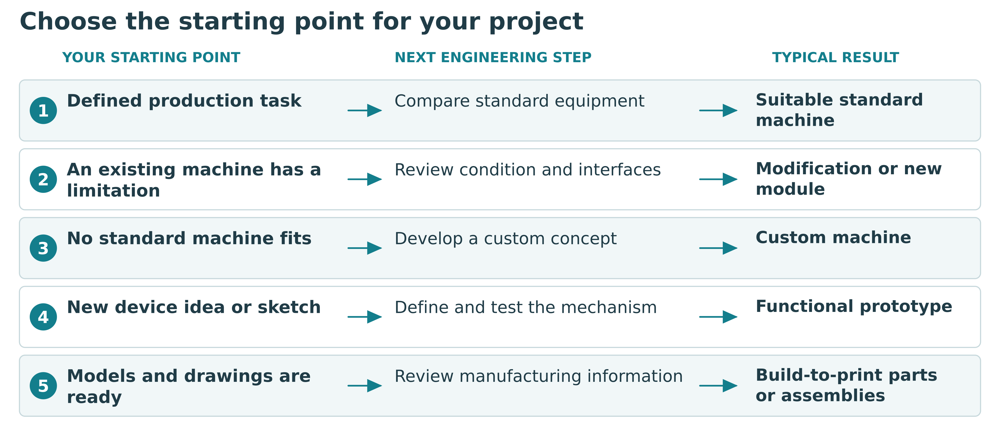
1 Choose the right starting point
Before searching for a custom machine manufacturer or a product development company, ask what is already defined. Do you know the product and process but need equipment? Is the operating principle still uncertain? Are the drawings complete and ready to manufacture?
Buying an existing machine
Standard equipment deserves consideration when an established machine can perform the required process with the actual product, available utilities and intended operating conditions. Compare its working range, changeover arrangements, cleaning access, loading method and downstream interfaces. Request trials with representative samples where these are important to the purchasing decision.
A published output figure alone does not establish suitability. A filling machine, for example, must handle the behaviour of the liquid and container as well as the requested volume. Product changeovers and cleaning can also influence the output achieved across a working shift.
Commissioning custom machinery
Custom machine manufacturing becomes relevant when available equipment cannot accommodate the product, process sequence, required motion or installation space. Special-purpose machines can combine operations such as feeding, positioning, filling, pressing, cutting, assembling and checking in an application-specific arrangement.
An existing machine may also be modified or extended. A new feeding module, fixture or transfer station can sometimes address the identified limitation. The condition and interfaces of the existing equipment need review before this route is selected. Our custom machine design and development service covers these starting points.
Developing a new product or building from drawings
A new device needs decisions about its functions, mechanisms, users and manufacturing approach. A build-to-print project starts with supplied design information and focuses on manufacturing review, procurement, assembly and inspection. If essential dimensions or interfaces remain undefined, engineering preparation should be included before production is quoted.
Table 1 Compare project starting points
| Route | A useful starting condition | What to check before committing |
|---|---|---|
| Standard machine | An available configuration appears to cover the operation. | Trials with the actual product, changeover, cleaning and line interfaces. |
| Existing machine upgrade | A specific limitation is identified in equipment already in use. | Machine condition, interfaces and the effect of the modification. |
| Custom machine | The process, product or layout needs an application-specific system. | Required functions, concept, build scope and acceptance conditions. |
| New device prototype | A new mechanism or product function needs physical evaluation. | The question to be tested and the functions included in the first build. |
| Build-to-print | Models and drawings are ready for manufacturing review. | Materials, tolerances, interfaces, assembly information and inspection requirements. |
Select the route after reviewing the actual requirement and the available equipment.
2 Define the result before choosing components
A useful brief describes the outcome in terms that both the buyer and engineering partner can check. Include the product or material being processed, current operation, required result, intended users and expected working conditions. Add representative samples, photographs or video wherever they explain something that words alone cannot.
For machinery, define the production target together with the available working time, product variations, loading arrangement and acceptable quality. State the available floor space, access routes and interfaces with upstream and downstream equipment. Existing electrical supplies, compressed air and other utilities influence the possible solution.
For a device, explain its intended use, principal functions, approximate dimensions and expected frequency of operation. Identify the feature that presents the greatest uncertainty. This may be a sealing mechanism, a dosing arrangement, a moving assembly or the interaction between a sensor and a sample.
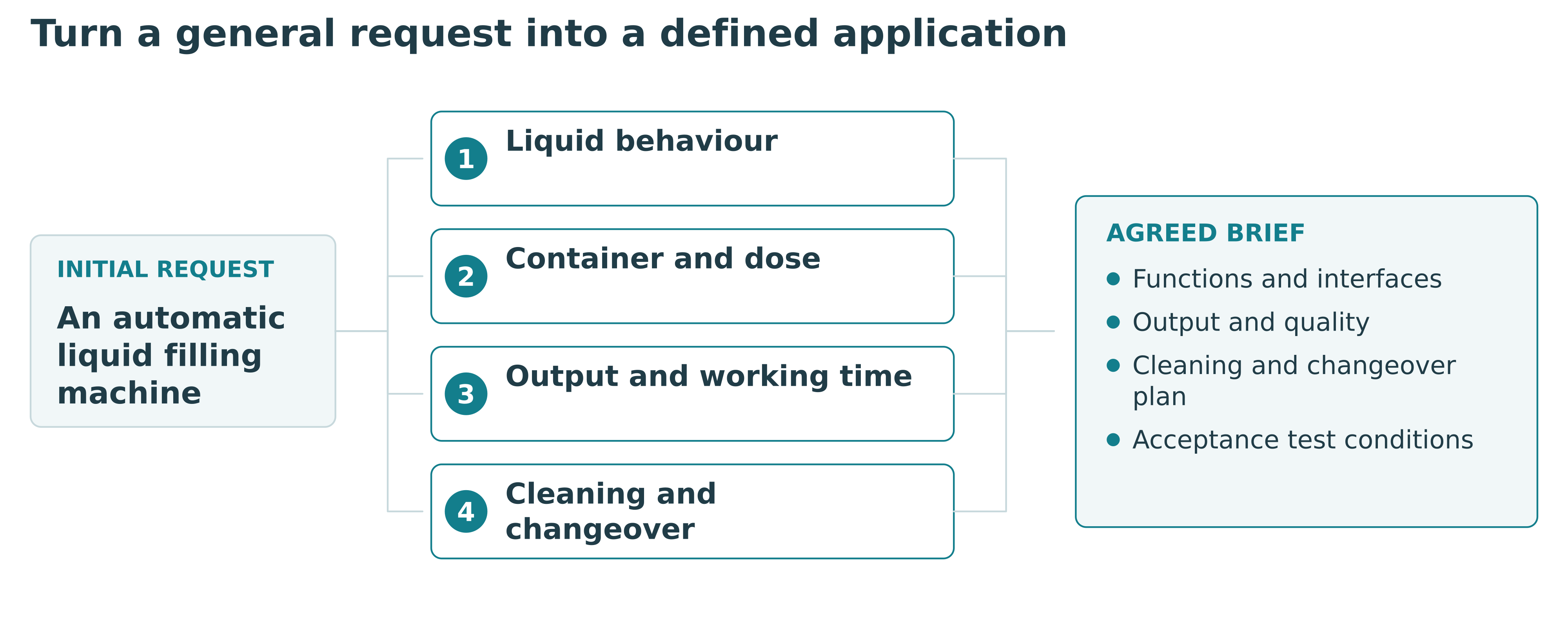
Consider an illustrative filling enquiry. The initial request is simply an automatic liquid filling machine. A useful brief adds the liquid properties, container drawings, dose range, required output, changeover needs and cleaning procedure. It also defines what will be measured during acceptance. Our liquid filling machine configurations provide a starting point for discussing such an application.
Separate confirmed requirements from preferences and questions. This helps the engineering partner compare concepts and avoids building an expensive feature around an assumption. Record agreed changes as the project develops so that the design, quotation and acceptance plan describe the same system.
Table 2 Make a filling machine enquiry specific
| Input | An illustrative description | Why it changes the engineering work |
|---|---|---|
| Product | A liquid that can foam or change behaviour with temperature. | Dosing method, trials, product handling and cleaning. |
| Container | More than one bottle shape or opening. | Guides, fixtures, nozzle access and changeover. |
| Output | A target quantity within a stated working period. | Cycle, number of operations and loading arrangement. |
| Cleaning | Contact parts must be accessible for a defined cleaning method. | Disassembly, surfaces, seals and access. |
| Acceptance | Checks use agreed samples and a defined measurement method. | A result that both parties can evaluate against the same conditions. |
This is an illustrative enquiry structure rather than a specification for a delivered QDM machine.
Site information for the technical brief
| Site information | What to share | Why it matters |
|---|---|---|
| Electrical supply | Available voltage, frequency and phases. | Electrical design and component compatibility. |
| Compressed air | Available pressure, flow and air preparation. | Pneumatic functions and utility provision. |
| Installation area | Space, access routes and operating environment. | Layout, delivery access and service clearance. |
| Adjacent equipment | Transfer heights, product orientation and connection points. | Mechanical transfer and station interfaces. |
| Existing controls | PLC details, communication interfaces and available drawings. | Integration scope and specialist responsibilities. |
Share the information available. Unknown values can be identified during the technical review; this list is not a fixed machine specification.
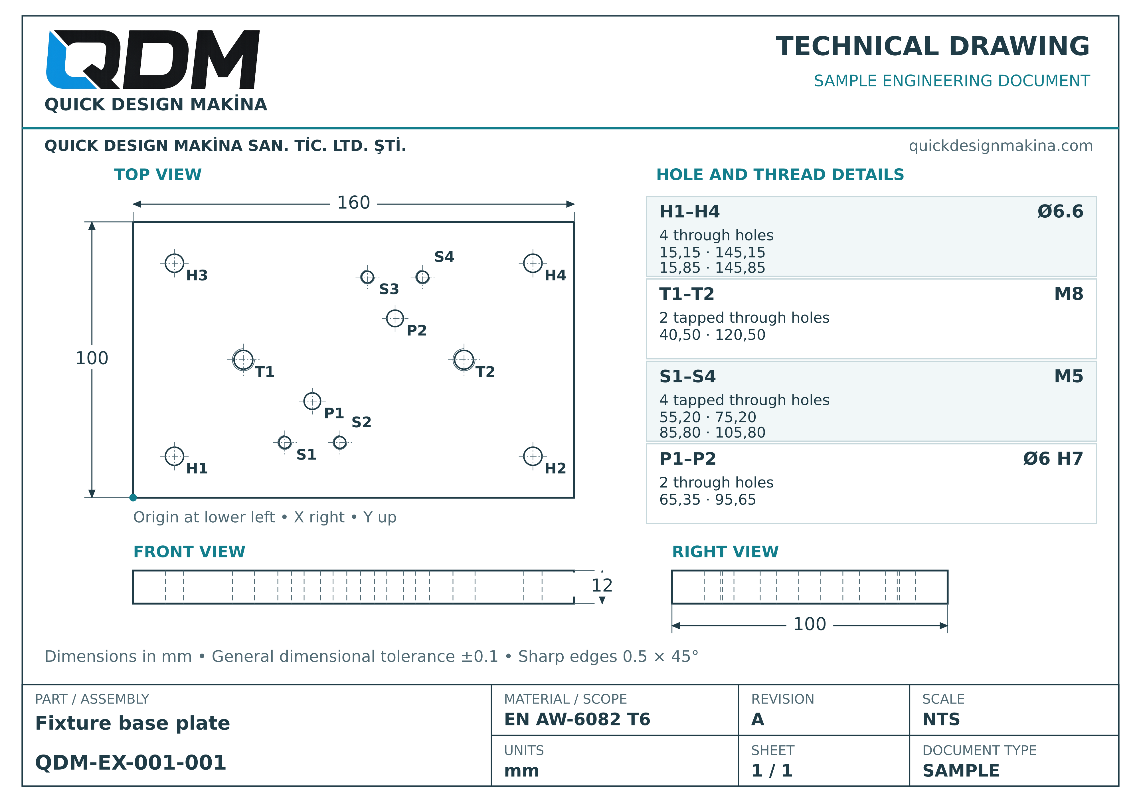
QDM technical drawing example
This example shows dimensioned views and hole information for a fixture base plate using QDM’s document heading. Part number QDM-EX-001-001 also appears in the sample BOM in the manufacturing section.
Project steps from the first discussion to delivery
The starting point determines which stages the project needs. Manufacturing from completed drawings and developing a new mechanism require different work. Use the table below to discuss the scope and the output to be reviewed at each stage.
| Stage | Customer information or decision | Output to review |
|---|---|---|
| Requirements and scope | Product, current operation, target output, space and open questions. | Requirements, work boundaries and proposal scope. |
| Concept and early trials | Critical uncertainties, samples and priority objectives. | Concept comparison and trial findings where needed. |
| Design review | Layout, interfaces and design decisions to be agreed. | 3D model, drawings, bill of materials and revision record, as included in scope. |
| Procurement and manufacturing | Timely decisions on information and changes that affect the build. | Fabricated parts, purchased components and manufacturing checks. |
| Assembly and testing | Representative products, samples and previously defined acceptance criteria. | Operating trials, check results and required corrections. |
| Acceptance and shipment | Review of results, delivery terms and destination information. | Acceptance record, agreed documents and shipment plan. |
Installation, commissioning, training or support at the final site are planned separately where required. The proposal defines the deliverables, review points and responsibilities for each stage.
3 Develop compact devices and larger machines around their actual use
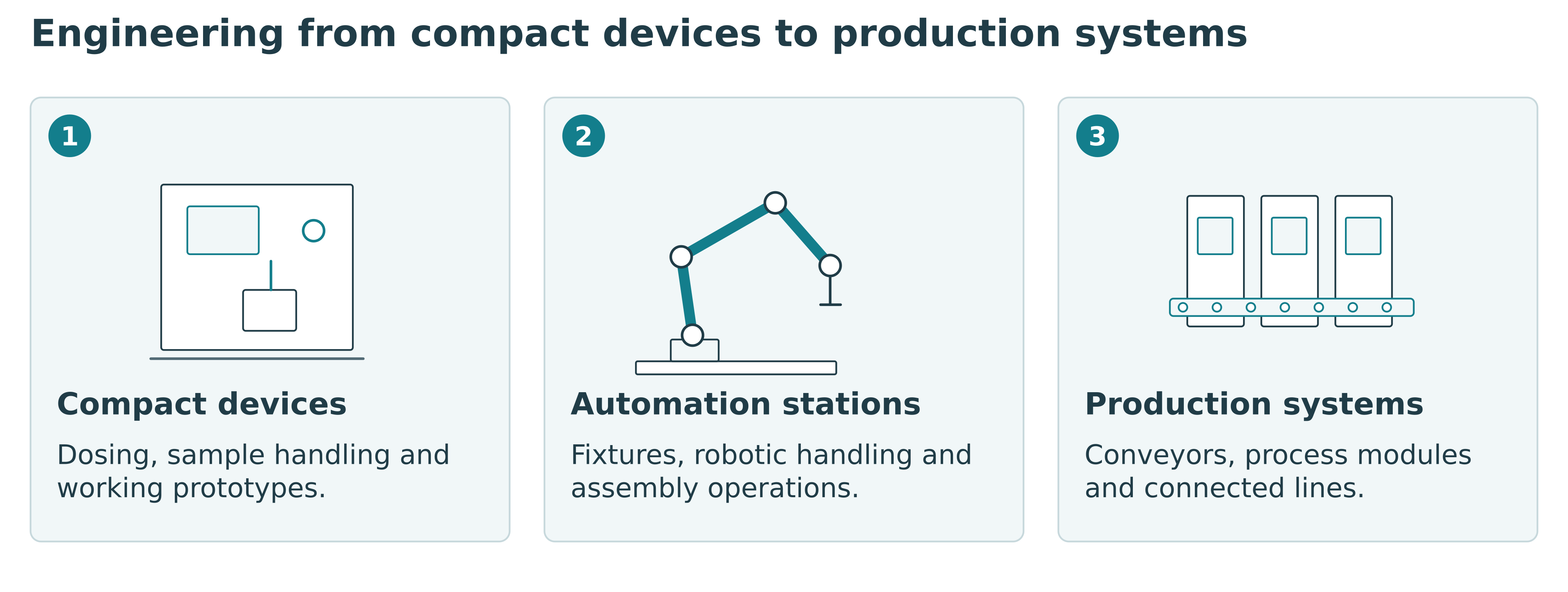
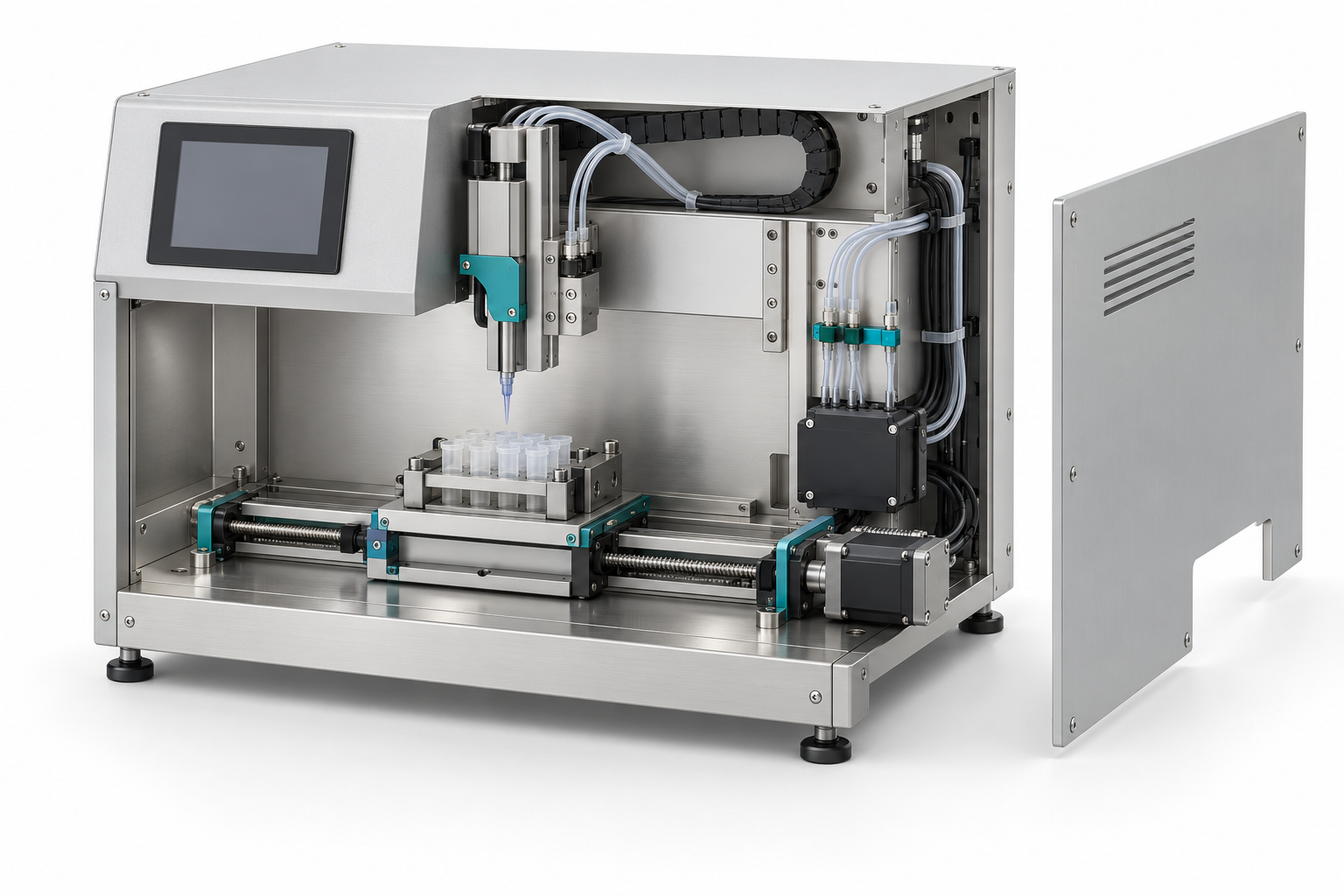
The physical size of a project does not explain its engineering difficulty. A compact dispenser may combine several interacting mechanisms in a confined enclosure. A larger machine may require careful frame design, material handling, access and installation planning. Both need decisions about manufacture, assembly, controls and testing.
Small device development can include dosing equipment, sample-handling mechanisms, analysis-device assemblies, laboratory equipment and motorised products. Space constraints make cable routing, bearings, seals, fasteners, heat, assembly access and component replacement important early considerations. A visually compact design still needs room for real parts and service operations.
Larger machinery can include conveyors, assembly stations, food-processing equipment, packaging modules and integrated production lines. Here, product flow, structural support, operator access and the interaction between stations become central design questions. A line layout must leave practical access for loading, cleaning, adjustment and removal of components.
An analysis instrument also needs a clear division between mechanical development and the measurement method. Sample positioning, motion and enclosure design can be developed alongside the customer's analytical expertise. Measurement performance requires its own agreed verification work.
We can discuss a compact device or a larger machine within the same project framework. Our device and product development service connects requirements and mechanical design with prototyping and manufacturing preparation. The selected scope can cover one development stage or continue through an agreed build.
4 Select motion systems for the load and operating cycle
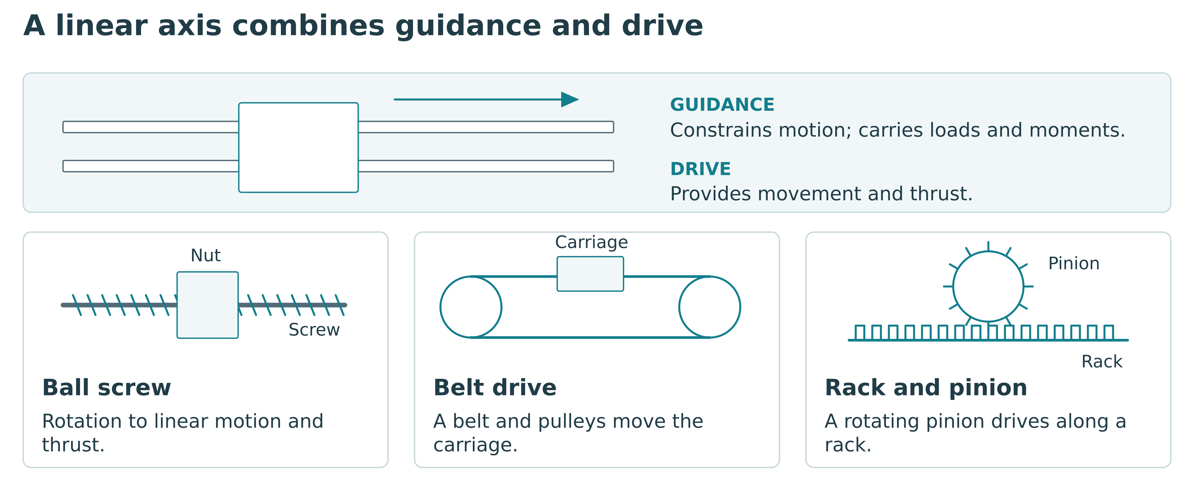
Linear motion systems bring together guidance, drive, structure and control. The guide constrains the motion and supports the applicable loads and moments. The drive supplies movement and thrust. A rail and carriage alone do not define a complete positioning axis.
Ball screws, belt drives and rack-and-pinion systems are among the options for translating motor rotation into linear movement. Selection requires the travel, load, speed, acceleration, duty cycle, positioning needs and installation conditions. Support arrangements, lubrication, contamination protection and maintenance access also affect the complete assembly.
Table 3 Distinguish linear guidance from drive options
| Element | Role in the axis | Information needed for selection |
|---|---|---|
| Linear rail and carriage | Guidance and support for applicable loads and moments. | Load directions, moments, mounting, environment and required life. |
| Ball screw | Transmission of rotary motion into linear movement and thrust. | Travel, axial load, speed, support, lubrication and positioning needs. |
| Belt drive | Transmission for a moving carriage through a belt and pulleys. | Travel, dynamic load, tension, stiffness and positioning needs. |
| Rack and pinion | Transmission through a rotating pinion and a linear rack. | Travel, loading, mounting, alignment, backlash and lubrication. |
Guidance and transmission are selected together. A component type alone does not establish complete-axis performance.
A short positioning task with a defined pressing operation may call for a different arrangement from a long transfer axis. A gantry carrying an offset tool must also accommodate the moments produced by that tool. Motor selection should follow the complete mechanical demand, including acceleration and transmission behaviour.
Servo motors, stepper motors, gearboxes and feedback devices can be considered within the control concept. Required repeatability, settling time and fault detection should be defined for the application rather than assumed from a component name. Accuracy and repeatability describe different aspects of performance and should be specified accordingly.
For custom actuators, rotary mechanisms and multi-axis assemblies, the output interface matters as much as the drive. Mounting surfaces, shaft connections, bearing support and the load imposed by the customer's equipment must be reviewed together. The result is an axis or mechanism designed for its actual operating conditions.
5 Combine pneumatic hydraulic and electric systems where they fit
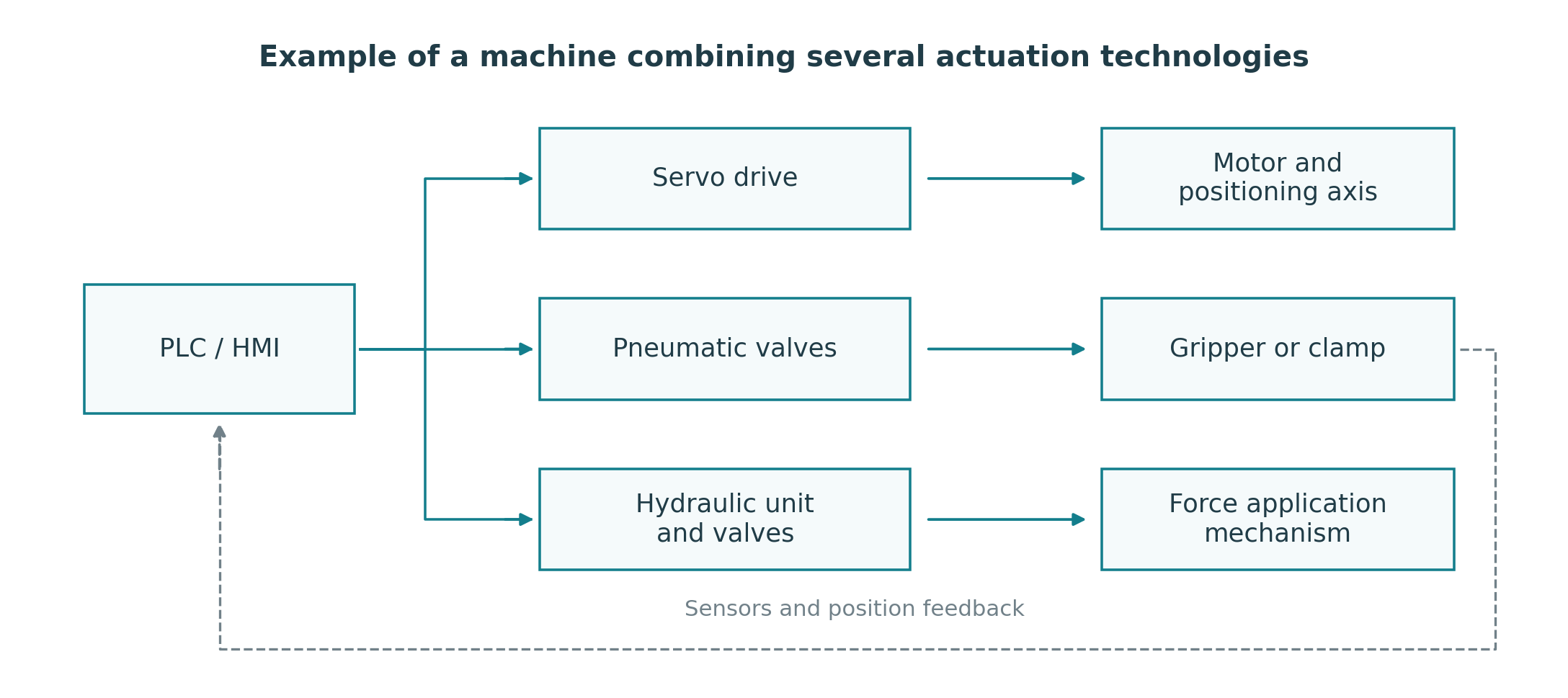
Many machines use more than one actuation technology. Pneumatic cylinders may operate clamps or gates while electric axes position the product. A hydraulic system may be considered for an application with substantial force requirements. The choice follows the operation, available utilities, desired control and maintenance conditions.
Table 4 Compare actuation technologies by the task
| Technology | Example functions | Questions to resolve |
|---|---|---|
| Pneumatic | Clamping, stops, gripping and end-position transfer. | Available air supply, load, stroke, speed control, sensing and air preparation. |
| Hydraulic | Pressing, lifting or another force application where appropriate. | Force and motion, pressure and flow, thermal conditions, fluid management and maintenance. |
| Electric | Programmable positioning, speed profiles and coordinated axes. | Motion demand, transmission, drive, feedback and controls integration. |
Several technologies can be combined in one machine. Compare the complete operating cycle and installation.
Pneumatic systems can serve gripping, stopping, lifting, clamping and transfer functions. Their design needs an assessment of the load, movement, working pressure, speed control, sensing and air preparation. End-position movement and controlled positioning involve different requirements; both need a suitable system architecture.
Hydraulic mechanisms require coordinated consideration of the cylinder or actuator, pressure and flow, power unit, valves, filtration and heat. Hoses and fittings need practical routing and protection. Maintenance access, fluid containment and the working environment belong in the initial layout discussion.
Electric actuation can be useful when the task calls for programmable travel, speed profiles or coordinated axes. It still needs appropriate mechanical transmission, feedback where required, and suitable control integration. Compare the complete installation and operating cycle when assessing alternatives.
For an illustrative assembly station, pneumatic clamping could hold the part while a motorised axis performs a controlled movement. The fixture establishes the part position, sensors confirm relevant conditions, and the control system manages the sequence. The engineering work lies in making those functions operate together consistently.
6 Plan robotic automation around the entire operation
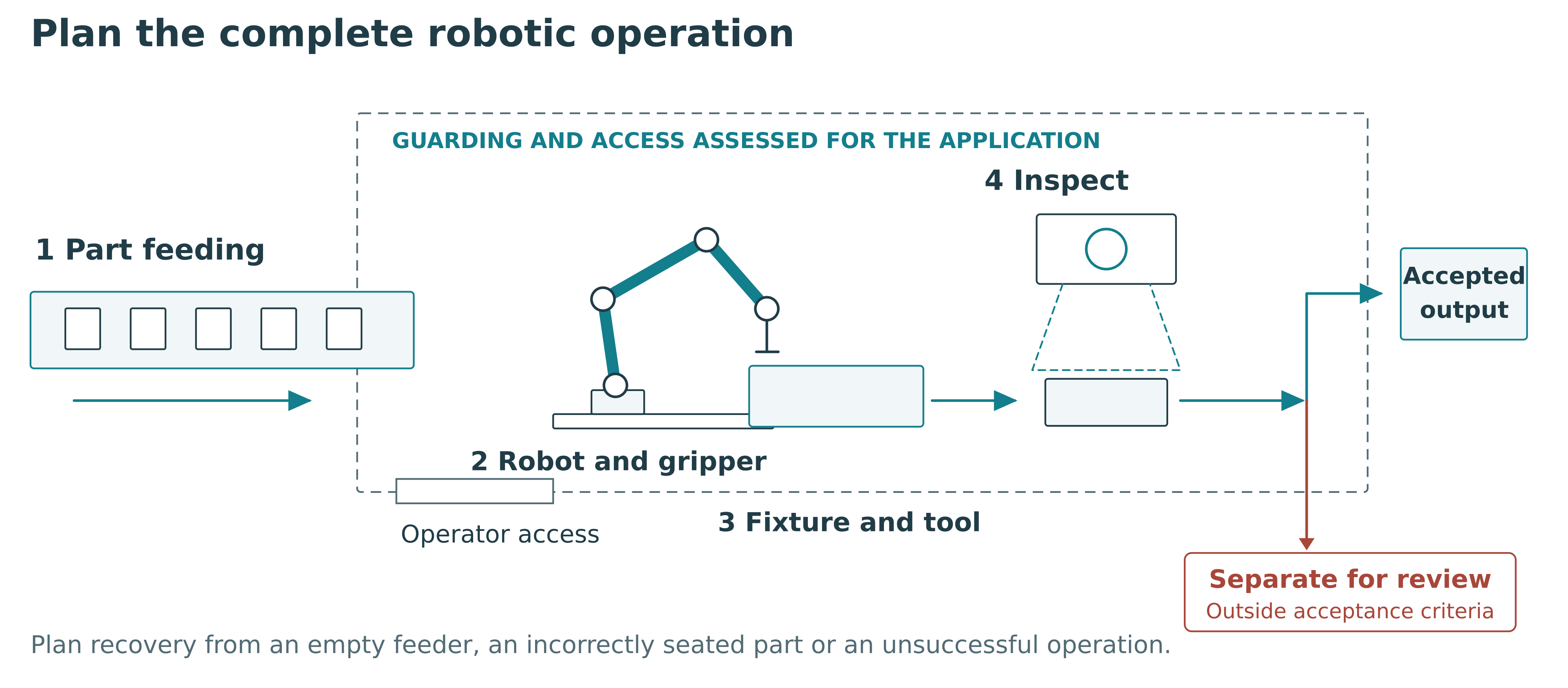
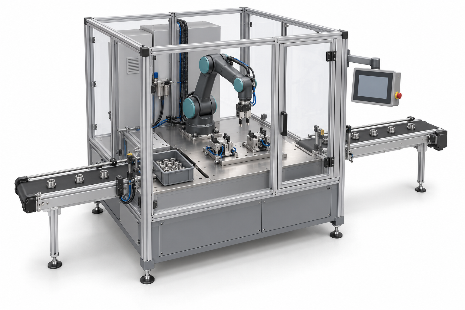
A robotic automation project includes the way parts arrive, how they are located and held, the tool that acts on them, and what happens when something goes wrong. A robot's reach and payload are only part of that assessment. The gripper, fixture, cables and product orientation also influence the usable working envelope.
Applications can involve pick-and-place, machine loading, handling, assembly or transfer between processes. Depending on the task, an articulated robot, a Cartesian gantry or dedicated motion mechanism may be considered. The choice should reflect product variety, access, required movements, cycle time and future changeover needs.
Take an illustrative assembly operation with several product variants. A workable concept needs a way to present each component, a locating fixture, suitable gripping and confirmation that the assembly step has succeeded. Tool changes or interchangeable fixtures may be needed. Recovery from an empty feeder or incorrectly seated part should be planned alongside the normal cycle.
Guarding, access arrangements and safety functions must be assessed for the complete application. A collaborative robot designation does not establish the safety of its tool, workpiece or surrounding process. Intended interaction with operators needs to be included in the system assessment.
Our automation and production systems service can cover an individual station, machine module or broader integrated system. Mechanical work, robot programming, electrical design and PLC or HMI implementation are assigned within the agreed project scope.
7 Build assembly stations and production lines around product flow
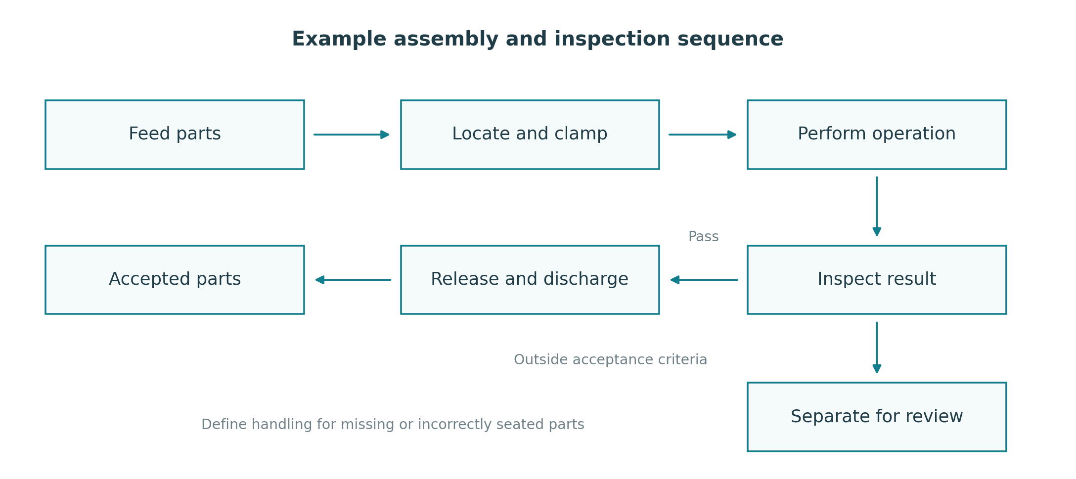
Production-line design begins with the sequence of operations and the relationship between them. A fast station can still spend time waiting if feeding, loading, inspection or discharge cannot support it. Review the whole process, including planned stops and manual tasks, before selecting the arrangement.
Assembly automation may involve rotary indexing, linear transfer, pressing, screwdriving, dispensing, joining and checking. Semi-automatic stations can retain operator loading while automating the process step. A fully automatic concept requires a reliable way to present and handle each component throughout the sequence.
Conveyors connect stations but also need application-specific decisions. Product stability, accumulation, transfer gaps, orientation, access and the surrounding environment affect their design. Belt, chain and modular conveyor arrangements serve different handling needs. Explore our conveyor systems when defining the transfer between operations.
A useful line review asks what happens during changeover, replenishment, a downstream stop and the removal of a rejected product. It also identifies where operators need to reach the equipment. These conditions help determine buffers, interfaces and the information exchanged between stations.
Expansion can be planned in stages. An initial station may solve the main process problem while leaving defined interfaces for future feeding, inspection or packaging modules. The proposal should identify which expansion provisions are included in the first build.
8 Develop food machinery and laboratory equipment for the working environment
Food devices and machines can involve preparation, dosing, mixing, filling, handling, cutting and packaging. The product's behaviour influences the mechanism, while the cleaning method influences surfaces, joints, access and disassembly. Material suitability needs to be assessed for the actual contact conditions and cleaning agents.
For an illustrative sticky-food handling task, a successful motion sequence alone is insufficient. Product release, residue, temperature variation and the time required to clean contact parts can change the practical result. Representative material trials are useful when these behaviours are uncertain.
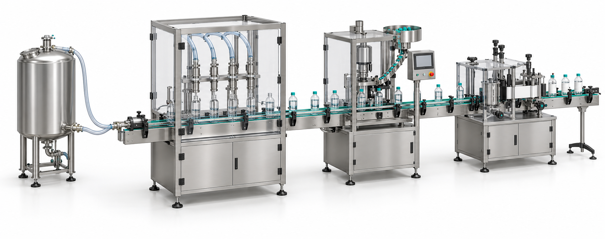
Hygienic design concerns the overall equipment arrangement, not only the choice of stainless steel. The European Hygienic Engineering & Design Group (EHEDG) publishes hygienic design guidance for food equipment, covering cleanability and the food-manufacturing environment. The relevant design and verification requirements should be identified for the particular application.
Laboratory and analysis-related devices raise another set of questions. Vessel size, sample retention, motion, vibration, loading access and cleaning may all affect the mechanical concept. Where the device supports an analytical method, agree which measurement functions the customer or specialist partner will define and verify.
QDM can develop application-specific mechanisms and equipment for these fields, with specialist input planned where required. The intended use and acceptance objective guide the work. A research prototype, a production-support device and equipment intended for commercial sale may require different development and verification plans.
9 Use prototypes to answer specific engineering questions
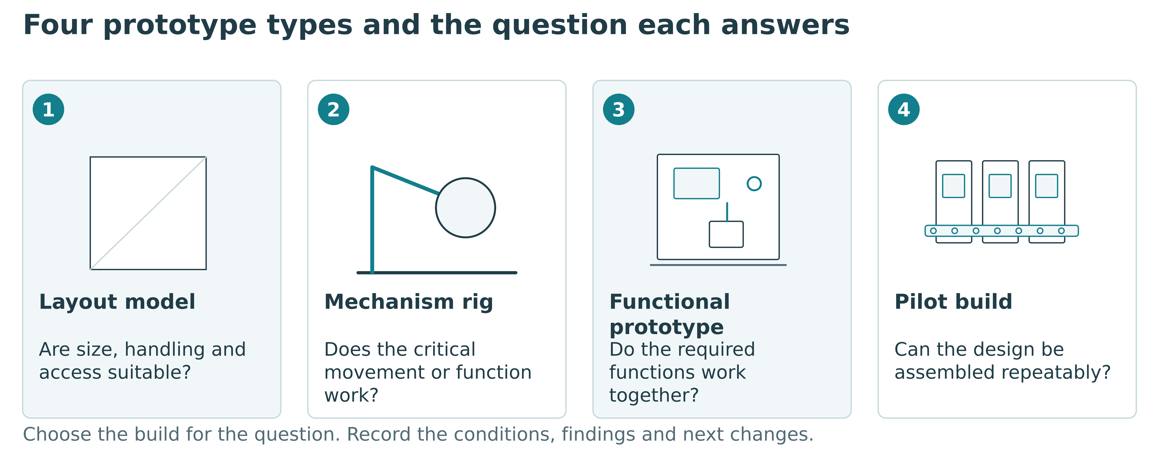
Prototype development starts with the question that needs an answer. A visual model can help assess size, handling and appearance. A mechanism prototype can test a critical movement. A functional prototype combines the features needed to evaluate the intended operation. A pre-production build examines the design using the proposed production arrangements.
These approaches can be used in sequence or combined where appropriate. A new benchtop dosing device, for example, might first need a rig that tests the dosing and sealing mechanism. Its enclosure can be developed around findings from those trials. If access and handling are the principal uncertainty, a physical layout model may be useful earlier.
Record the test conditions and what the prototype demonstrates. A successful short trial under one condition does not establish service life across every intended use. Prototype findings should identify the functions demonstrated, issues found and changes proposed for the next stage.
Consider assembly during the first build. Adjustments that make a prototype work may reveal missing tolerances, awkward access or a need for locating features. Capture those findings in the drawings and bill of materials so that a later build does not depend on the memory of the person who assembled the first unit.
Our prototyping and manufacturing service can cover individual parts, mechanisms, assembled devices and small batches. The prototype objective determines the build and trial scope. Preparation for repeat production can continue after the findings have been reviewed.
10 Choose manufacturing methods for the design and quantity
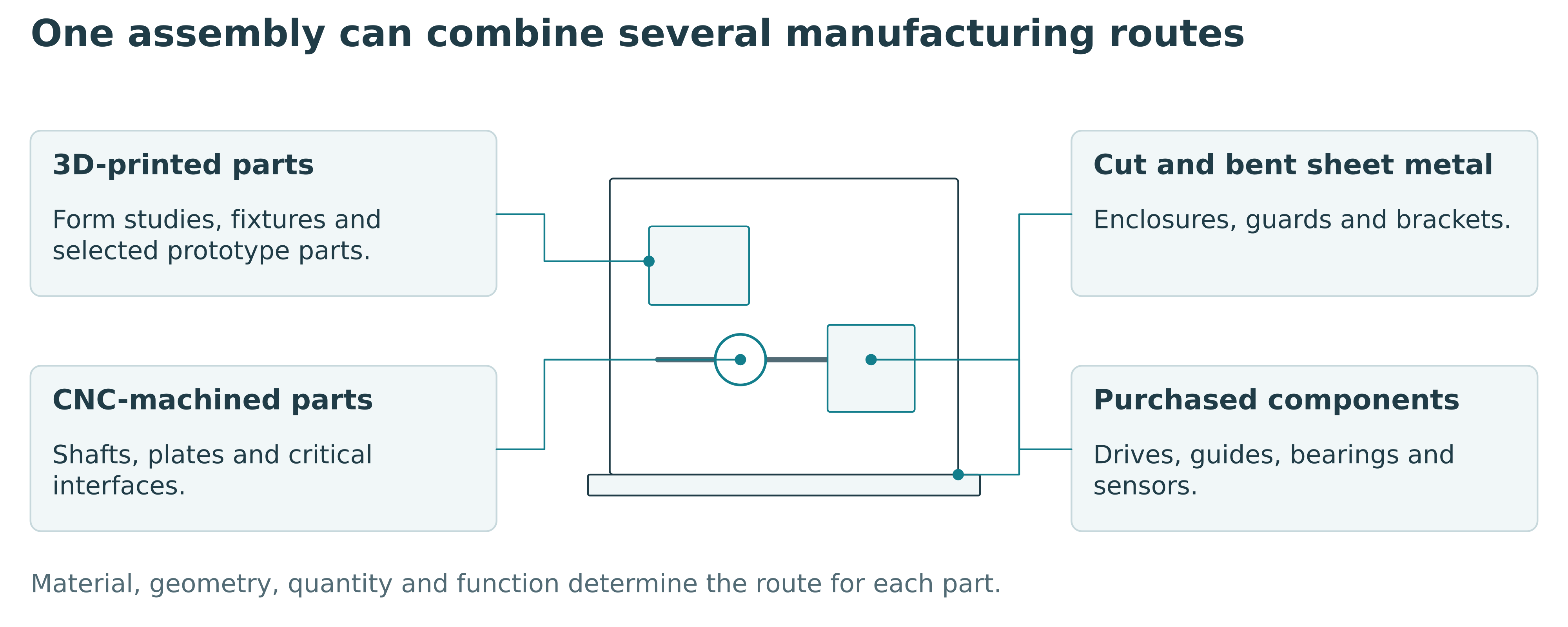
Prototype manufacturing and low-volume production can draw on machining, sheet metal fabrication, welding, additive manufacturing and purchased components. Each method needs consideration of material, geometry, tolerances, surface condition, quantity and assembly requirements. Several methods may be combined in one machine or device.
CNC machining can produce housings, shafts, plates and other mechanical parts from suitable stock. Drawings need to identify critical dimensions and interfaces. Tool access, workholding and the sequence of operations influence the manufacturing approach. Assigning tight tolerances to every surface can add work without improving the required function.
Laser-cut and bent sheet metal can serve enclosures, guards, brackets and structural parts. Bend access, fastening, edge treatment and assembly sequence should be considered in the design. Welded structures need attention to fit-up, distortion, accessible joints and any subsequent machining requirements.
3D printing can support form studies, fixtures and selected functional prototype parts where the material and process are appropriate. Consider build direction, surface condition, temperature, loads and the purpose of the trial. A successful printed sample does not automatically establish how a moulded or machined version will behave.
The preferred manufacturing route may change with production quantity. An early enclosure might use machined or fabricated parts while a later production design is reassessed for other processes. Compare tooling, development effort, unit cost and expected quantities before making that transition.
Design for manufacturing and assembly connects these decisions. Review part count, standard components, fastener access, adjustment and replacement while the design is still developing. A manufacturing partner should also raise unclear drawings or difficult features before parts are released to the workshop.
Table 5 Compare manufacturing routes for an early build
| Method | Examples of parts | Decisions before manufacture |
|---|---|---|
| CNC machining | Shafts, housings, plates and precision interfaces. | Material, critical features, tolerances, tool access and workholding. |
| Sheet metal fabrication | Enclosures, guards, brackets and supporting parts. | Thickness, bend access, connections, edges and assembly sequence. |
| Welded fabrication | Frames and supporting structures. | Fit-up, distortion, joint access and subsequent machining. |
| 3D printing | Layout models, fixtures and selected prototype components. | Material, build direction, surface, loads, temperature and trial objective. |
A suitable prototype process may differ from the process selected for repeat production.
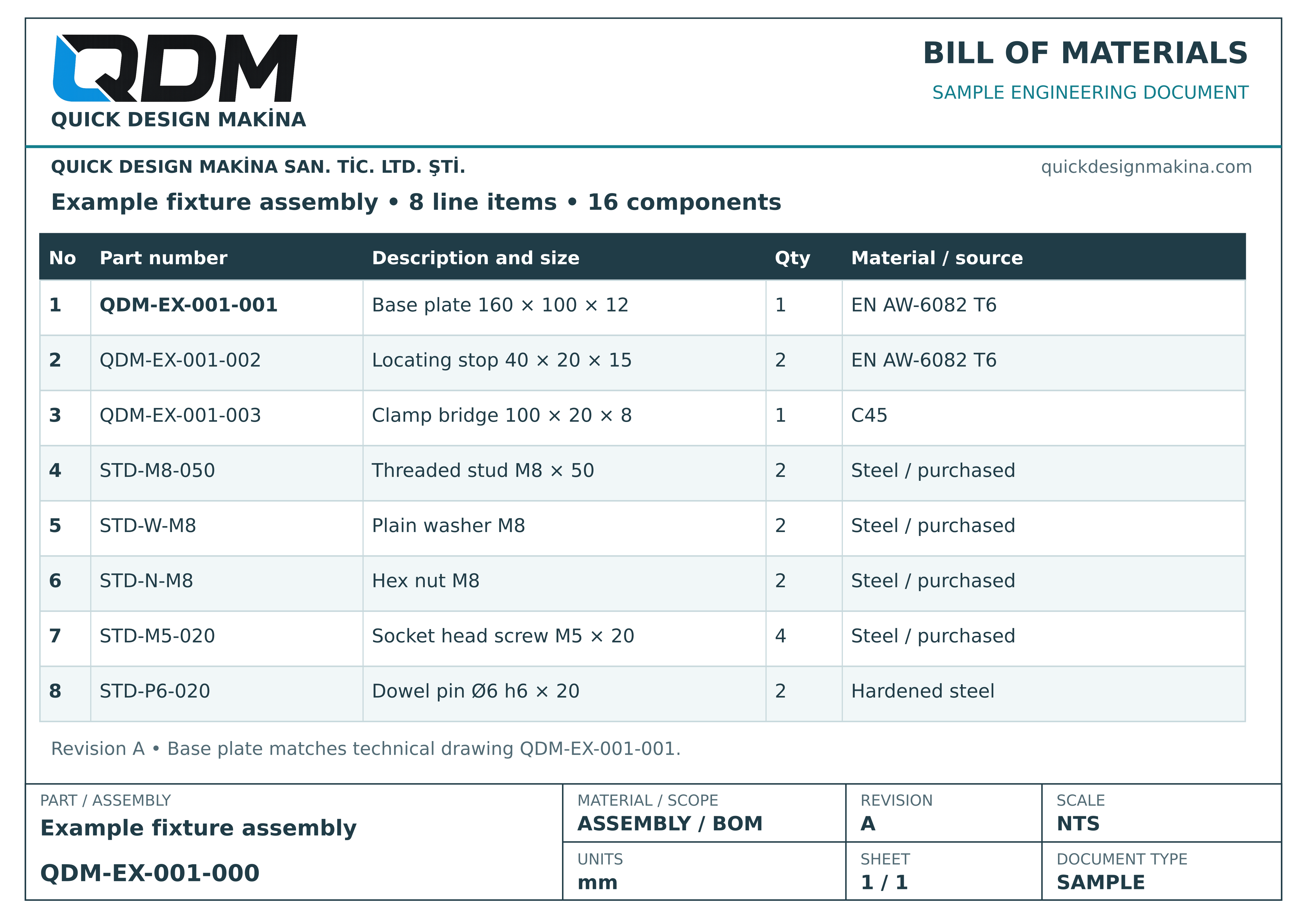
QDM bill of materials example
The BOM for the same example fixture brings together manufactured parts and purchased components by part number and quantity. Base plate QDM-EX-001-001 links the list to the technical drawing.
11 Understand development cost and manufacturing cost separately
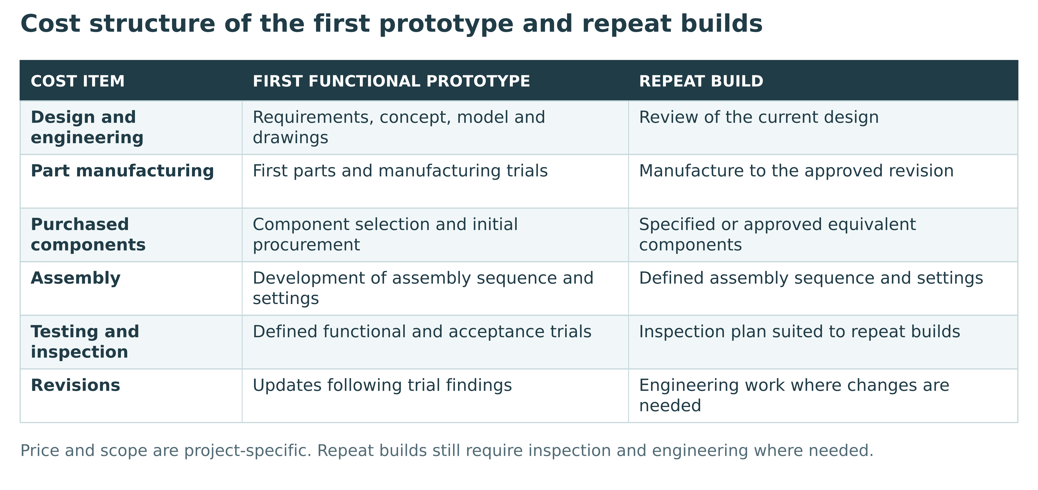
A quotation for a new product or custom machine can contain several different types of cost. Engineering covers work such as requirements review, concept development, mechanical design and manufacturing documentation. The build covers fabricated parts, purchased components, assembly and the agreed trials. Tooling, specialist integration and delivery can add further items.
An initial functional prototype therefore has a different cost structure from a repeat unit made from a stable design. Development work is needed before the first build exists. Later units still depend on the final design, procurement quantities, manufacturing process and inspection arrangements.
For machinery, major cost drivers can include the operations being automated, product variety, required performance, size, handling method and control scope. For a compact device, the interaction between tightly packaged mechanisms can create substantial design and assembly work even when its external dimensions are modest.
Lead time also has several parts. Requirements clarification and design reviews precede procurement and fabrication. Purchased-component availability, supplier processes, assembly and trials influence the schedule. A plan should identify customer decisions and sample deliveries that the engineering team depends on.
When comparing proposals, check what each price includes. Look for the number and purpose of builds, included revisions, trial conditions, documentation and delivery arrangements. A lower figure with an incomplete scope may leave essential work for a later quotation. The quotation and delivery guide should be read with the actual project proposal.
12 Select a partner for the work your project requires
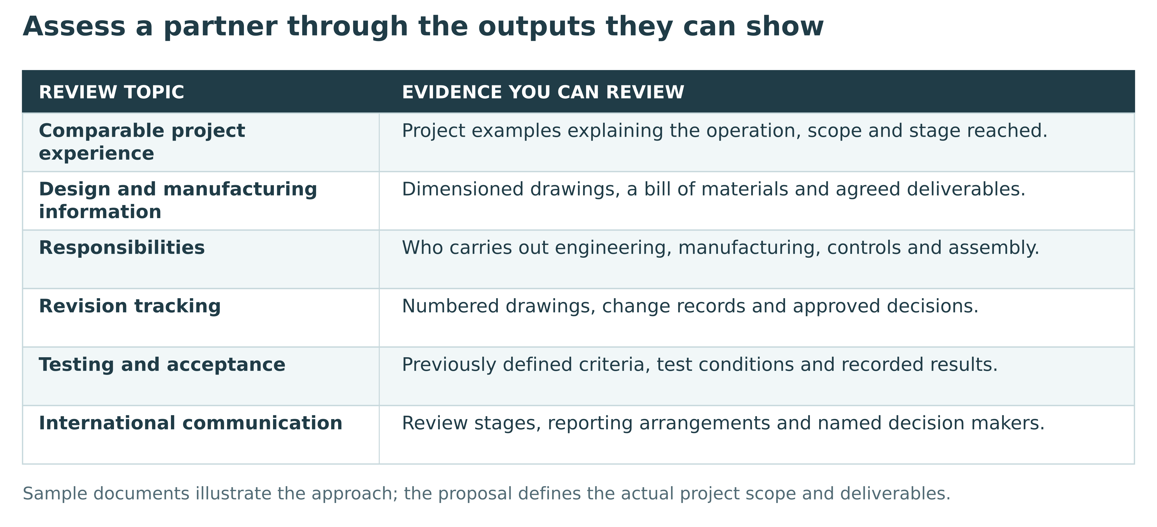
Relevant experience is more useful than a long equipment list. Ask a prospective machine builder or product development partner to explain a comparable mechanism, process or integration problem. Understand what they designed, what was manufactured and which development stage was reached.
Clarify how the project will be delivered. One company may lead the mechanical engineering while specialist partners provide fabrication, controls or electronics. The buyer needs a named coordination point and a clear division of responsibilities. Ask how supplier queries, design changes and acceptance issues will be managed.
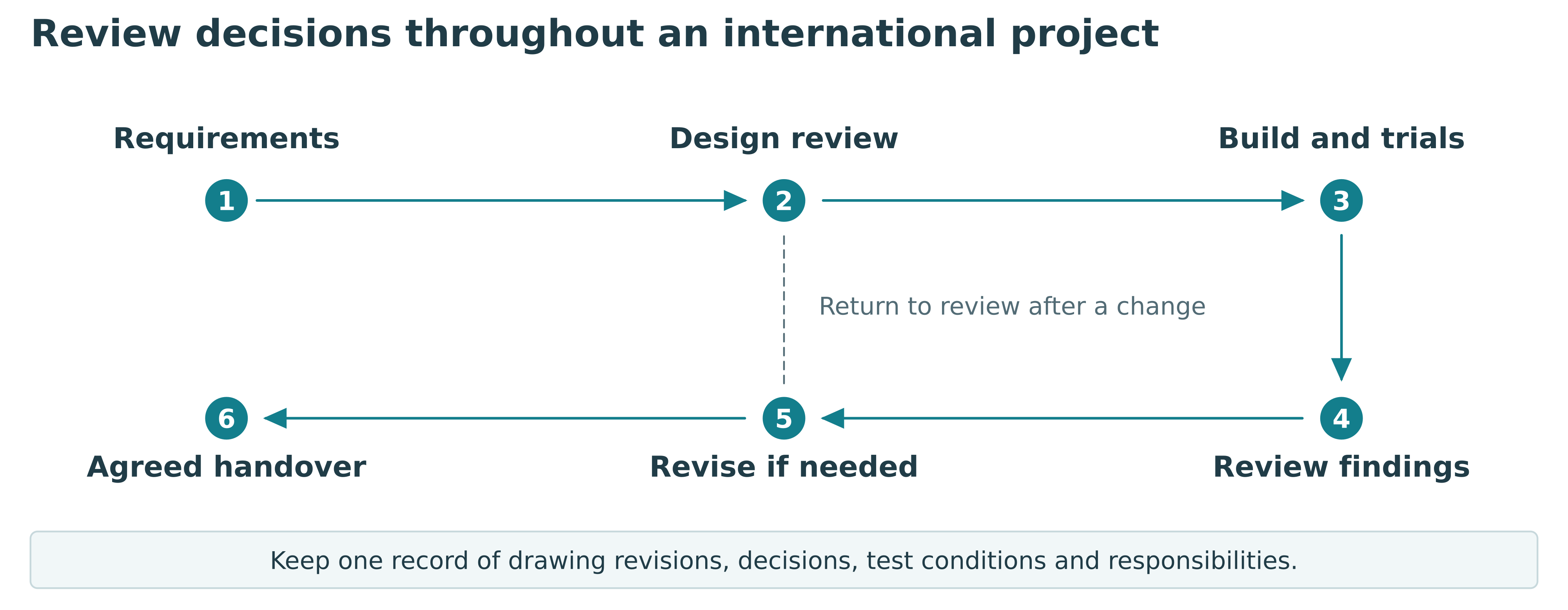
International projects also depend on practical communication. Identify the people who can approve changes, the review information they need and the expected reporting arrangements. Use numbered drawing revisions and documented decisions to keep remote reviews connected to the parts being manufactured.
At QDM, mechanical development and project coordination can be combined with manufacturing and specialist partners selected for the work. The engineering services overview sets out the main areas. Project deliverables, specialist tasks and the route to delivery are then defined for the particular requirement.
13 Plan machinery sourcing and manufacturing in Turkey
An international buyer looking for a machine manufacturer in Turkey should begin with the same technical brief used to assess any supplier. Location becomes useful when connected to the actual manufacturing, communication and delivery plan. Compare the complete project rather than assuming an advantage from country alone.
For a design and manufacturing project in Turkey, confirm where engineering, part production, assembly and trials will take place. Establish how the buyer will review the design and witness relevant tests. Remote meetings, progress photographs and test videos can support the process, with visits or sample shipments arranged where necessary.
Shipping should be discussed while the equipment layout is developing. Dimensions, mass, lifting points, transport protection and any disassembly influence the handover plan. Confirm which party arranges packing, transport and destination activities. Installation and commissioning need their own practical arrangements when included.
Destination requirements also belong in the project discussion. Identify the intended use, necessary documentation and any specialist conformity or validation work. The quotation should state the work and responsibilities that have been included. General manufacturing capability alone does not establish suitability for every market or application.
QDM is based in Istanbul and is open to international machine, device and manufacturing projects. Our machinery sourcing and manufacturing guides for Turkey provide related reading for buyers comparing equipment and planning an enquiry.
Comparing a project based in Turkey
Compare communication, procurement arrangements and delivery against the same technical brief when assessing a manufacturing partner in Turkey. Discussing the following information with QDM makes the working arrangements for an overseas project clearer.
| Comparison topic | Information to agree | Effect on the project |
|---|---|---|
| Communication and approvals | Working language, meeting times, decision makers and reporting frequency. | A shared record of design decisions and changes. |
| Procurement arrangements | QDM’s work, manufacturing partners’ tasks and specialist contributions. | Proposal scope, responsibilities and coordination. |
| Remote review | Drawings, progress photographs, test videos and a visit plan if needed. | Comparison of the built system with the reviewed design. |
| Shipment and final site | Responsibilities for packing, transport, customs formalities, unloading and installation. | Comparable delivery scope and destination preparations. |
CE marking and destination requirements
The destination country and intended use determine the applicable legislation and required documents. Machinery placed on the EU market and falling within the relevant legislation is subject to Machinery Directive 2006/42/EC before 20 January 2027 and Machinery Regulation (EU) 2023/1230 from that date. The transition requires consideration of when the product is placed on the market and its regulatory scope.
CE marking requirements are assessed for the particular product. Work on the required risk assessment, technical file, conformity assessment and declarations is defined in the proposal and project agreement, taking account of each party’s statutory obligations. The delivery point in Turkey does not remove mandatory product safety and conformity obligations applicable to the product.
European Commission — official source on machinery legislation
14 Look at project outcomes and development stages
QDM's published project examples show how requirements can lead to different engineering tasks. Each example has a stated delivery or development status.
The multi-nozzle liquid filling project addressed viscous liquids, small doses and filling workflow. QDM developed the mechanical design and coordinated procurement and automation; manufacturing and assembly involved project partners. The line was delivered.
The orbital shaker project was delivered for viscous liquids in 1 L bottles, with bottle inclination adjustable up to 30 degrees. Mechanical development addressed the motion, bottle arrangement and application requirements.
The custom actuator development reached working-prototype stage. It illustrates mechanical development around motion, mounting and interfaces. Performance ratings and production readiness require application-specific verification.
Published project outcomes at a glance
| Project and requirement | QDM scope | Reached stage |
|---|---|---|
| Multi-nozzle filler Viscous liquids and small doses. | Mechanical design; procurement and automation coordination. | Delivered filling line. |
| Orbital shaker Viscous liquids in 1 L bottles. | Mechanical development of motion and bottle arrangement. | Delivered; bottle inclination adjustable up to 30 degrees. |
| Custom actuator Application-specific motion and interfaces. | Mechanical development and coordinated prototype build. | Working prototypes; application-specific verification remains necessary. |
Manufacturing and assembly involved project partners. Each status describes the stated project; it is not a universal performance rating.
These examples represent different kinds of work, from delivered equipment to prototype mechanisms. For your project, identify the comparable engineering challenge and the next result you need. Catalog renders and concept illustrations should be read according to their captions rather than treated as photographs of delivered machines.
15 Prepare for testing acceptance and repeat production
Acceptance starts with a definition of what will be checked. For machinery, the plan may cover operation with representative products, output under specified conditions, quality, changeover and interfaces with other equipment. For a prototype, the checks should follow the development question and agreed functions.
Record the conditions as well as the result. Sample characteristics, settings, run duration and measurement method affect what a test establishes. Define how issues will be recorded and how revisions will be reviewed. If installation is included, distinguish workshop checks from the work that requires the final site.
Table 6 Define what an acceptance check will establish
| Check area | Define before the trial | Record with the result |
|---|---|---|
| Machine output | Product, settings, test duration and handling conditions. | Quantity achieved, interruptions and relevant operating conditions. |
| Process or assembly quality | The characteristic to inspect and the method of evaluation. | Measured results, observations and nonconforming samples. |
| Changeover and cleaning | The products, tools and procedure included in the check. | Actions required, access issues and observations. |
| Prototype function | The mechanism or combined function to demonstrate. | Conditions tested, demonstrated behaviour and proposed revisions. |
| Line interfaces | Signals, transfers and the equipment involved. | Checks completed and any work remaining for the final site. |
The table is a planning aid. The project-specific acceptance plan defines the actual checks and limits.
For low-volume manufacturing or repeat production, update the design package after prototype changes. Review the bill of materials, purchased-component specifications, assembly sequence, inspection points and required fixtures. A repeatable build needs a shared definition of the product and its permitted variations.
Where manufacturing transfer is required, discuss it before development starts. The package may include drawings, assembly information, supplier specifications and support for pilot builds. File formats, permitted use and the information to be transferred are established in the project agreement.
16 Send the information needed for a useful quotation
You do not need to know every component before approaching an engineering partner. Share the information you have and explain the decision you need help making. A short description can establish the next stage; a firm build price needs a sufficiently defined technical scope.
For a machine or automation enquiry, send the product details, current operation, target output, available space and relevant photographs or video. For a new device, describe the intended use, essential functions, approximate size and prototype objective. For build-to-print manufacturing, provide available models and drawings, materials, quantities, critical requirements and delivery expectations.
Prepare information for your project route
| Project route | Useful initial information | Files or samples where available |
|---|---|---|
| Custom machine or automation | Product, current operation, target output, space and utilities. | Process video, representative samples, product drawings and layout. |
| New device or product | Intended use, essential functions, approximate size and prototype objective. | Sketches, reference products, an existing prototype and test observations. |
| Build to print | Required parts or assemblies, materials, quantities and critical requirements. | 3D STEP models, dimensioned 2D PDF drawings, bill of materials and inspection requirements. |
A first discussion can start with incomplete information. A firm manufacturing quotation requires an adequately defined scope.
Begin with non-confidential information when appropriate. An NDA can be discussed before detailed technical files are exchanged. If the project has a target budget or an important deadline, share it so that possible scope and staging can be assessed early.
Discuss your machine or product project with QDM. Tell us what you need to build, what already exists and which engineering or manufacturing stage you want to achieve next.
17 Engineering and manufacturing partnerships in Turkey
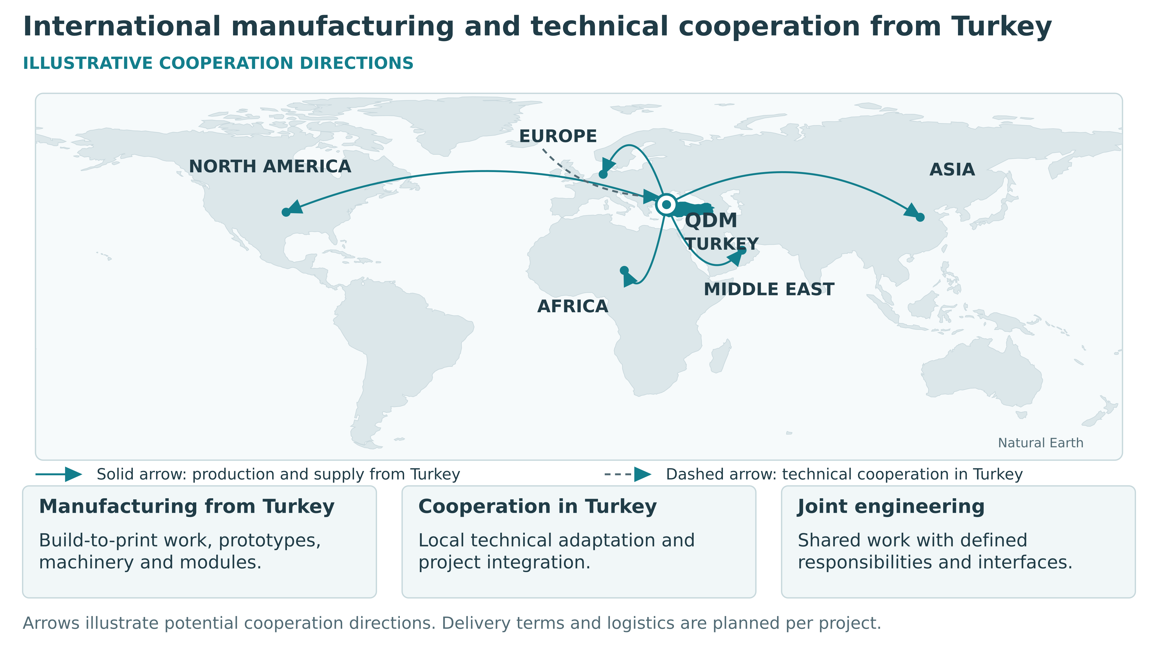
QDM is open to discussions with overseas machine manufacturers, engineering companies, automation integrators and product businesses. Cooperation can concern production in Turkey for an international project, support for equipment entering the Turkish market, or a defined engineering package within a larger contract.
Manufacturing in Turkey for overseas companies
Potential work includes build-to-print parts and assemblies, prototype manufacturing, small-batch products, machine modules and custom equipment. We can discuss mechanical development, procurement coordination and assembly around the partner's requirements. Branding, documentation, quality checks and delivery responsibilities are set out for the proposed arrangement.
Technical cooperation for the Turkish market
Overseas equipment manufacturers exploring sales in Turkey may need application review, customer-specific mechanical adaptations or local integration support. Technical sales cooperation, assembly, installation and service arrangements can be discussed according to the equipment and project. Any representation or distribution relationship requires a separate commercial agreement.
Joint engineering and automation projects
An automation company may need mechanical design, fixtures, handling modules or a coordinated machine build. A product developer may need a local engineering and prototype partner. Joint work can divide responsibilities between the companies so that interfaces, reviews and final deliverables are clear.
To begin a partnership discussion, introduce your company, markets and equipment or product range. Explain the role you would like QDM to take and whether the opportunity concerns a specific project or ongoing cooperation. Contact QDM about a partnership and include Partnership enquiry in your message.
Frequently asked questions
Can I start without CAD files or technical drawings
Yes. A description of the required function, sketches, photographs or a process video can support the first review. Engineering work may be needed to define the design before prototype manufacturing or a firm build quotation.
Can the project cover one small device or one custom machine
The scope can be discussed for a single prototype, mechanism, device or machine. Technical feasibility, components, manufacturing methods and the required trials determine the appropriate development and build plan.
Can you manufacture a design supplied by our engineering team
We can review supplied models, drawings and manufacturing requirements for a build-to-print scope. Missing dimensions, interfaces or assembly information are clarified before the relevant work is released.
Can robots pneumatics hydraulics and electric motion be combined
Yes. A machine may combine these technologies where the functions call for them. Component selection and integration follow the required load, motion, cycle, operating environment and control arrangement.
Can you develop food machines laboratory devices and assembly equipment
These are areas we can discuss. The intended process, materials, operating conditions and verification needs determine the scope. Specialist analytical, food-contact or market requirements are identified for the application.
Can you supply turnkey machinery
A turnkey scope can include design, procurement coordination, manufacturing, assembly and agreed integration and trials. Confirm the exact deliverables and whether packing, shipping, installation, commissioning and support are included in the proposal.
Can production continue after the prototype
Yes. Prototype results can inform design revisions and a new scope for low-volume production or preparation for larger quantities. Repeat production needs defined manufacturing, assembly and inspection arrangements.
Can an overseas company discuss a partnership in Turkey
Yes. We are open to discussions about engineering cooperation, manufacturing in Turkey, local technical integration and project-specific commercial collaboration. Introduce your company and the proposed division of work through the contact page.
How much does a custom machine or working prototype cost
Cost depends on the required operation, product variants, output, machine size, controls and amount of new development. Engineering, the first build, agreed trials and repeat units have different cost structures. Share the application and the stage you need so the proposal can define the work, deliverables and price.
How long does a custom machine or prototype project take
Lead time is defined after the scope, technical uncertainties, review stages and critical component availability are understood. Design decisions, procurement, manufacture, assembly and trials all affect the schedule. Share your target date early so the project can be staged and a delivery plan agreed.
Can an NDA be agreed and who owns the design
An NDA can be discussed before detailed technical files are shared. The project agreement defines the drawings and other files to be delivered, ownership, manufacturing rights and permitted use. Discuss these terms before development begins, especially if you intend to manufacture with another supplier.
How can we follow the project from overseas
The working language, reporting frequency, decision makers and review stages can be agreed at the start. Drawing revisions, progress photographs and test videos support a shared decision record. A live test connection or a visit can be planned where needed. Define what each review covers and which decisions require customer approval before the work proceeds.
How is machinery shipment from Turkey planned
Delivery is at the customs or terminal location in Turkey specified in the proposal and project agreement. The customer arranges onward transport. Responsibilities for packaging, export formalities and loading are specified in the proposal. On-site assembly, installation and commissioning follow the project agreement.
Terms used in this guide
The terms are explained for general information. The proposal and project agreement define the technical scope, delivery point, tests and on-site services for each project.
| Term | Meaning in this guide |
|---|---|
| Build-to-print | Manufacturing to customer-supplied models, drawings and technical requirements. Missing or conflicting information is resolved before production. |
| Turnkey | A delivery approach combining the engineering, manufacturing, integration and trials defined in the proposal. Installation and support are stated separately. |
| Fixture | A device that holds a part in a defined position during an operation or inspection. |
| Gripper | A tool that grasps and holds a part. A robot end effector may instead cut, drive screws or perform another operation; not every end effector is a gripper. |
| Functional prototype | A prototype built to test defined functions and how they work together. Readiness for production is assessed separately. |
| Pilot build | A limited build used to review the design, assembly method and production arrangements. |
| Factory Acceptance Test FAT | Checks at the manufacturing or assembly facility against previously defined conditions and acceptance criteria. |
| Site Acceptance Test SAT | Checks at the final installation site, with a previously defined scope that includes relevant site interfaces and operating conditions. |
Technical reading
Linear motion guidance and drive principles provides background on the roles of guiding and driving elements in linear systems.
EHEDG hygienic design principles introduces hygienic design considerations for food-manufacturing equipment and environments.
For application-specific equipment, explore the QDM machine and device catalogue and follow the product or service page relevant to your requirement.