Process and fixtures
Define the assembly sequence, part locations, tools and quality checkpoints.
A production-line concept joining a robot, rotary fixtures and guarded mechanical stations.
Enquire about this machineMachine & device catalog · Configuration agreed per project
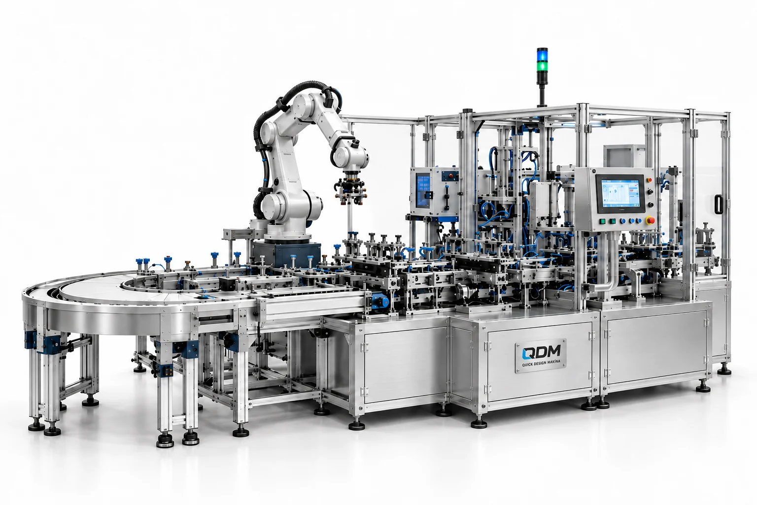
This assembly-line study brings robotic transfer and dedicated machinery into a connected mechanical layout. A rotary fixture area, handling robot and guarded stations provide a basis for discussing the sequence of a repetitive assembly process. QDM develops the mechanical scope and coordinates specialist controls and robot integration within the agreed project.
Define the assembly sequence, part locations, tools and quality checkpoints.
Develop the fixtures, station structures, carriers and equipment interfaces.
Coordinate robot, controls and protective-system responsibilities with the relevant partners.
Materials, dimensions, operating range, output, controls and delivery scope are confirmed in the project proposal.
Use these notes to define the application before choosing the final equipment configuration.
A robotic assembly line combines flexible transfer with fixtures and process stations designed for the product. Articulated robots are used for operations such as picking, placing and assembly; they still need suitable tools and a defined presentation of parts. QDM’s reference line shows a robot, rotary fixture area and guarded mechanical stations.
Describe the assembly sequence, part variants and required quality checks. Robot reach and payload need to include the end effector and operating path, while dedicated stations may set the overall cycle. A robot selection does not remove the need for locating fixtures or a practical method to feed components. Controls and robot integration are coordinated with project-specific specialists.
Development should review the transfer path and each assembly operation with representative components. Agree responsibilities for robot programming, electrical work and protective systems in the scope. Acceptance can include normal cycles, missing-part responses, recovery and documentation. QDM can lead the mechanical development and coordinate a turnkey project with those specialist responsibilities expressly defined.
The table identifies the reference arrangement and the values to agree for your application.
| Parameter | Configuration / value | Confirm before manufacture |
|---|---|---|
| Assembly sequence | Defined per product | List steps and quality checkpoints |
| Robot selection | Application-specific | Review reach, payload and tooling |
| Fixtures | Part-specific nests and locating features | Provide variants and interfaces |
| Part presentation | Trays, feeders or carriers as scoped | Define orientation and replenishment |
| Cycle objective | Agreed line cycle in seconds | Include all process dwell times |
| Specialist integration | Defined partner and client responsibilities | Agree controls and robot scope |
| Acceptance and recovery | Project-specific procedures | Define trial parts and exception handling |
These products are customizable. Configuration values and images are indicative and may change with the application. Final dimensions, components, controls and performance requirements are confirmed in the agreed project specification.
Representative CAD and generated design visualizations. These are not photographs of delivered equipment. Illustrated arrangements may change with customization; final values and visuals are confirmed in the project specification.
QDM supplies equipment with a standard one-year machine warranty, starting from commissioning.
Purchased components are covered under the relevant manufacturer’s warranty terms. Two-year component coverage applies where provided by the manufacturer; coverage and start dates follow those terms.
Extended warranty and maintenance agreements can be arranged for the project. Coverage, duration, service responsibilities and commercial terms are agreed in the contract.
The quotation and contract define the equipment covered, the applicable warranty terms and the agreed service arrangements.
Send part drawings, the process sequence, current operation video, cycle target and available floor space.
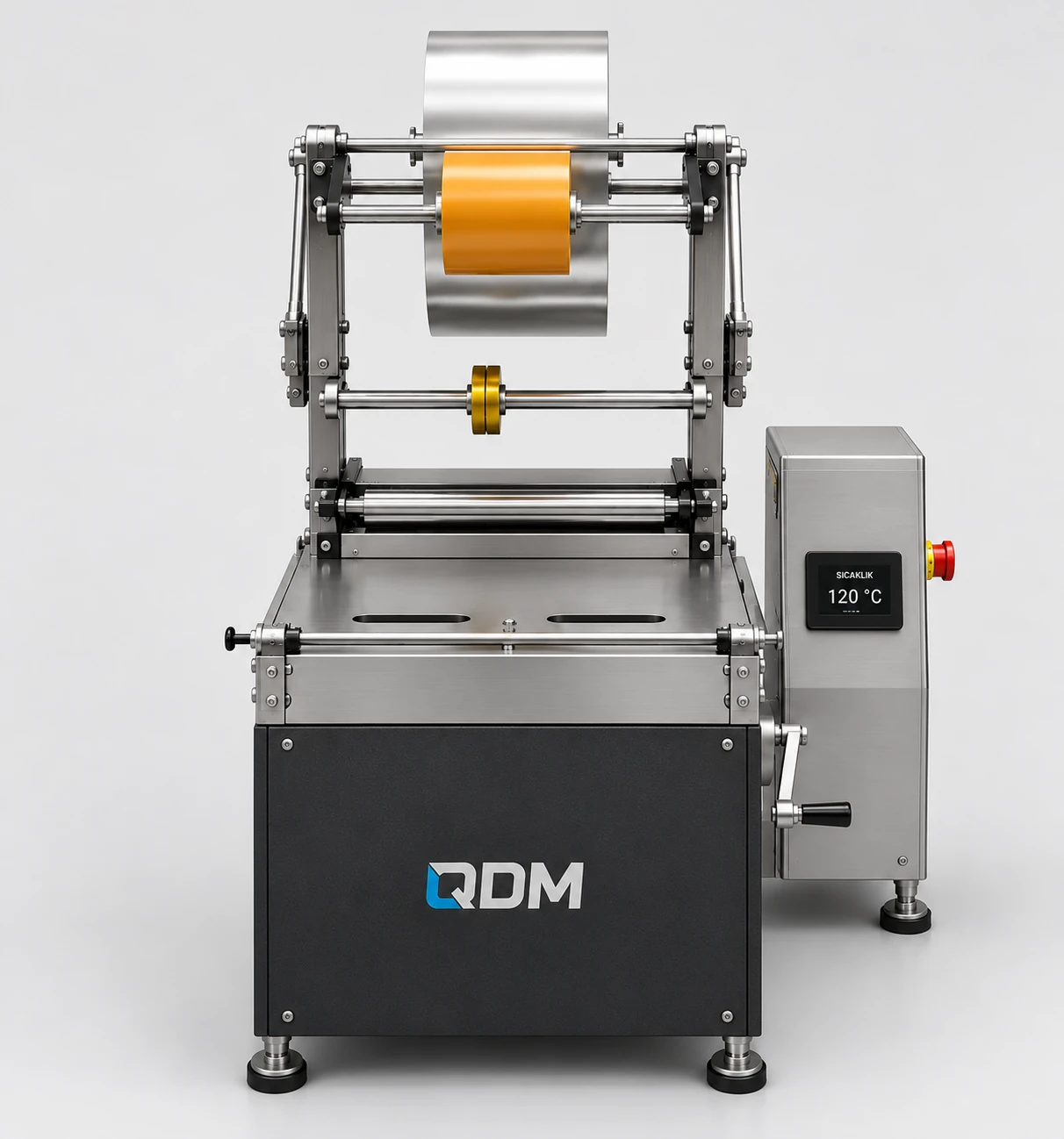
A compact semi-automatic layout for roll-fed wrapping and heat-sealing operations.
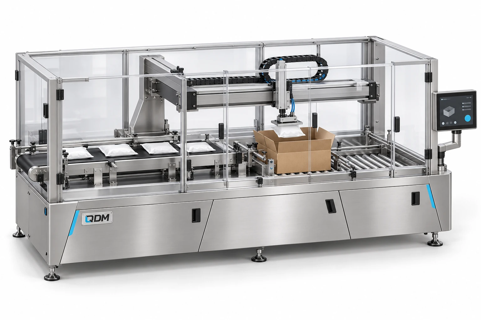
A conveyor-based case-loading layout with overhead product handling.
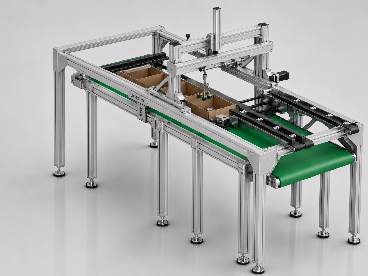
An overhead handling mechanism integrated with a belt-based workstation.