Payload and geometry
Define the equipment footprint, load distribution and required adjustment.
A supported platform concept for positioning equipment on uneven working surfaces.
Enquire about this conceptMechanical integration concept · Configuration agreed per project
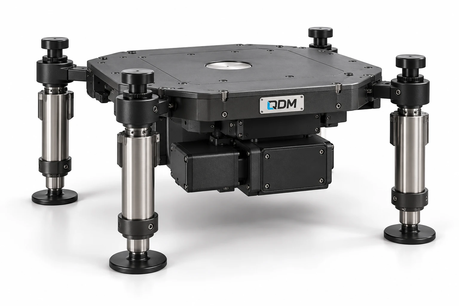
This concept combines an equipment mounting platform with individually adjustable supports. It provides a basis for developing a stable reference surface where equipment position and ground conditions vary. Actuation, feedback and any automatic levelling functions are scoped around the actual payload and operating need.
Define the equipment footprint, load distribution and required adjustment.
Develop the platform, legs, mounting and actuation interfaces.
Agree sensing, controls and verification for any required automatic functions.
Materials, dimensions, operating range, output, controls and delivery scope are confirmed in the project proposal.
Use these notes to define the application before choosing the final equipment configuration.
An adjustable levelling platform positions a supported surface using a defined mechanical arrangement. Coordinated screw-jack systems illustrate how several lifting points can move together. QDM’s reference platform is a starting point for discussing load support and adjustment; the actual drive, travel and control method must be selected for the application.
Specify the supported equipment, centre of gravity and the surface that should be level. Vertical travel and tilt adjustment are separate requirements. Multiple supports need an agreed coordination approach to avoid an unintended difference in height. Manual adjustment, powered movement and automatic levelling should be treated as distinct configurations.
Development should review structure, support reactions, travel limits and holding behaviour under the specified load. Agree the levelling target and how it is measured. Include access for adjustment and maintenance, plus any control interfaces, before manufacture. QDM can scope a mechanical platform and coordinate selected actuators without claiming automatic levelling or a universal lifting capacity for the concept.
The table identifies the reference arrangement and the values to agree for your application.
| Parameter | Configuration / value | Confirm before manufacture |
|---|---|---|
| Supported load | Defined in kg and distribution | Provide equipment and centre of gravity |
| Platform envelope | Configured in mm | Confirm mounting and useful area |
| Adjustment travel | Defined in mm or degrees | Separate lift and tilt requirements |
| Actuation | Manual or powered as selected | Review load and holding method |
| Support coordination | Defined per configuration | Agree linked or independent adjustment |
| Level target | Application-specific | Define measurement and acceptance |
| Controls and limits | Included where scoped | Agree travel stops and interface |
These products are customizable. Configuration values and images are indicative and may change with the application. Final dimensions, components, controls and performance requirements are confirmed in the agreed project specification.
Representative CAD and generated design visualizations. These are not photographs of delivered equipment. Illustrated arrangements may change with customization; final values and visuals are confirmed in the project specification.
Send equipment dimensions and loads, ground conditions, adjustment requirement and available utilities.
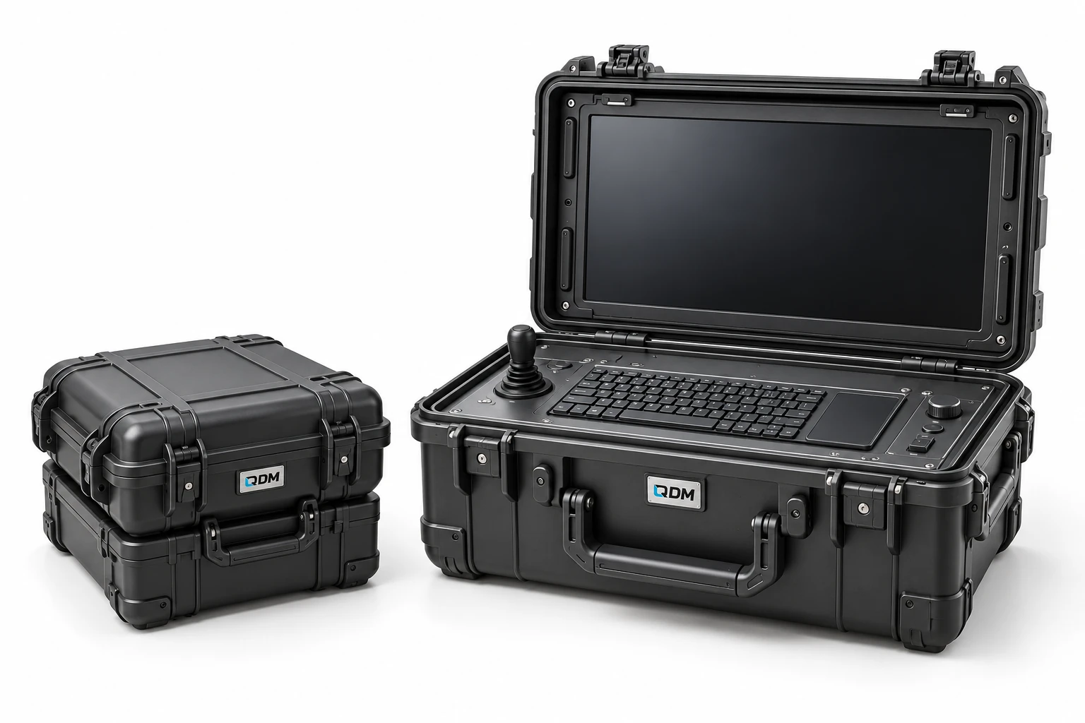
A transport-case concept for integrating operator equipment into a portable workstation.
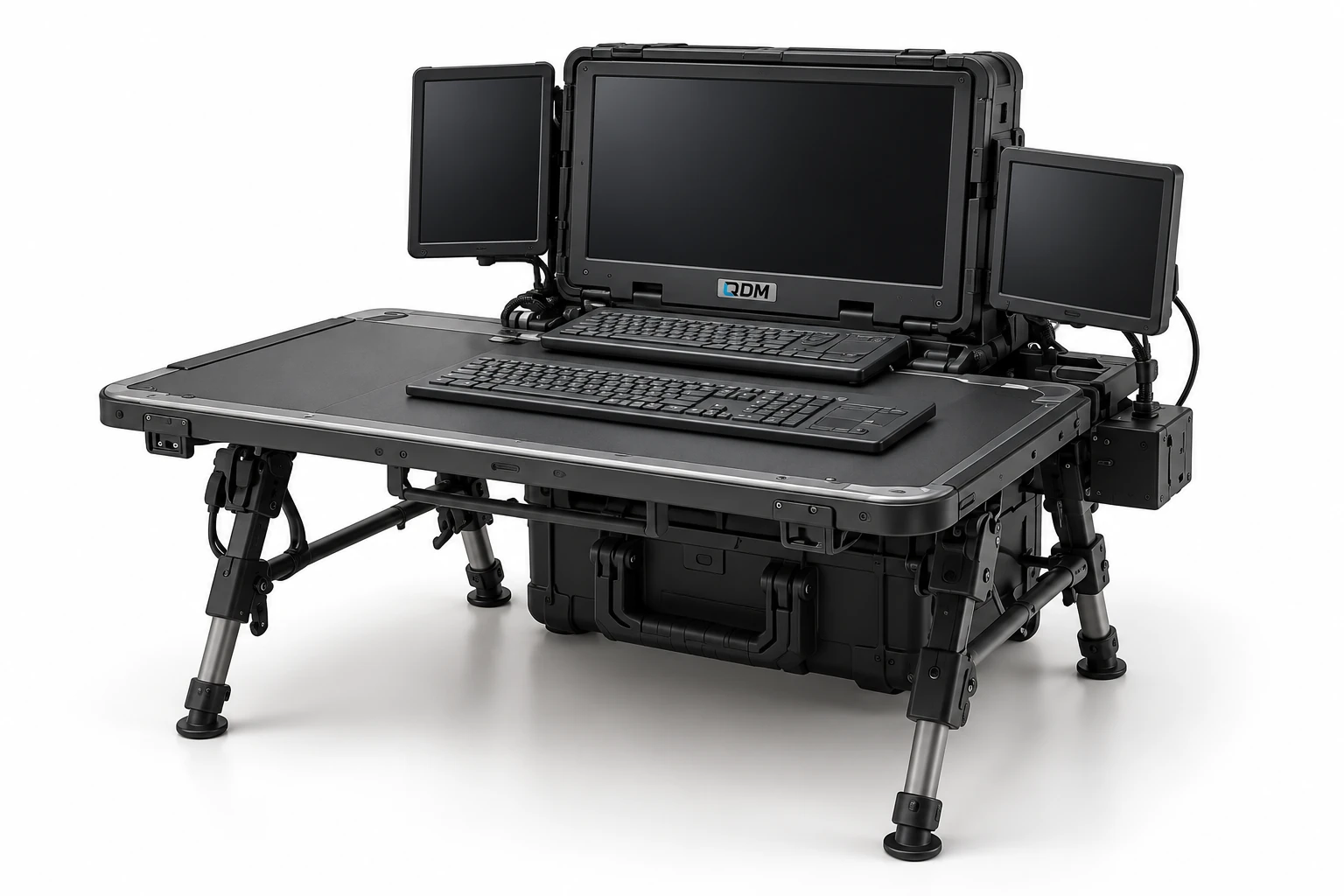
A folding work-surface and equipment-support concept for field deployment.
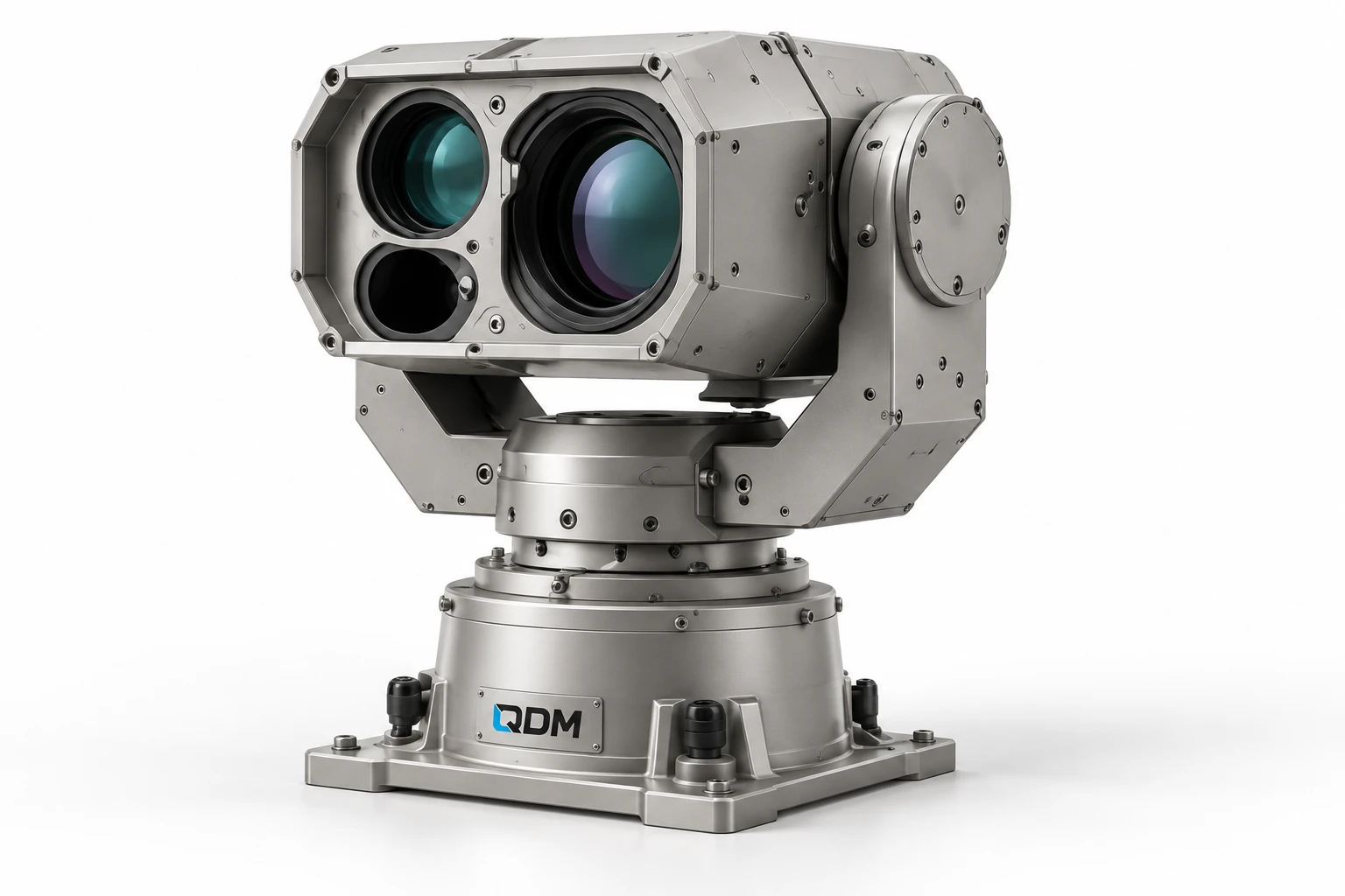
A mechanical positioning concept for customer-selected cameras, instruments or sensor payloads.