
Use and transport
Define the working arrangement, packed envelope and equipment to carry.
A folding work-surface and equipment-support concept for field deployment.
Enquire about this conceptMechanical integration concept · Configuration agreed per project
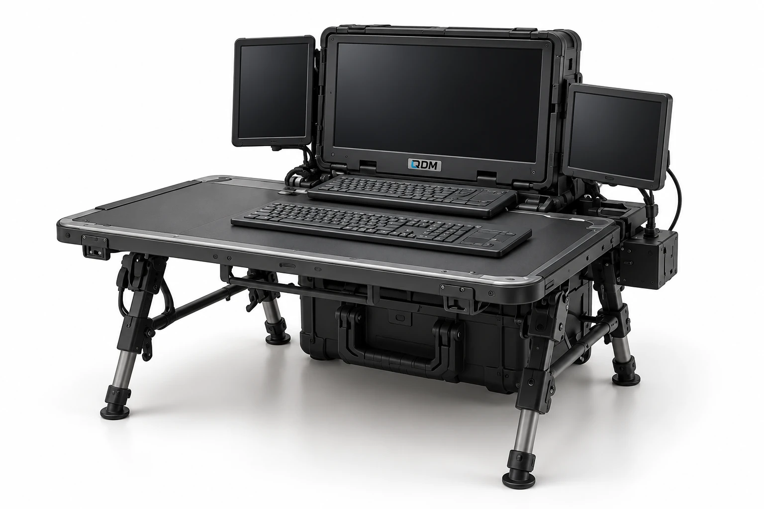
The fold-out workstation study combines transportable equipment with a supported work surface and a folding base. It illustrates mechanical development for equipment that must move between storage, transport and use configurations. Load, stability, access and setup requirements drive the design.
Define the working arrangement, packed envelope and equipment to carry.
Develop folding members, joints, work surface and mounting interfaces.
Agree load cases, stability objectives and checks for the intended environment.
Materials, dimensions, operating range, output, controls and delivery scope are confirmed in the project proposal.
Use these notes to define the application before choosing the final equipment configuration.
A fold-out workstation provides a working surface and component storage in a layout that can be packed for transport. Commercial mobile office cases illustrate folding and storage arrangements; the QDM concept is developed from the intended technical task. Deployment convenience must be considered alongside stable support and practical access during use.
State the tools, devices and working operation before selecting the table or frame layout. Packed dimensions and mass affect handling, while working height and surface area affect the task. Folding mechanisms should have defined locked positions and clearance for cables. The intended ground or support surface is also part of the requirement.
The first build should be reviewed through opening, locking, working and packing. Agree the permitted working load, equipment retention and inspection points for repeated setup. Outdoor or transport qualification is a separate test requirement rather than a feature established by a render. QDM can scope the mechanical workstation and coordinate any separately defined powered or specialist equipment.
The table identifies the reference arrangement and the values to agree for your application.
| Parameter | Configuration / value | Confirm before manufacture |
|---|---|---|
| Working task | Client-specific technical operation | List tools and equipment |
| Packed size | Defined in mm | Confirm transport and storage |
| Working surface | Configured dimensions and height | Review reach and access |
| Working load | Defined in kg and load distribution | Agree support and stability checks |
| Deployment mechanism | Folding and locking as scoped | Review setup and clearance |
| Equipment retention | Application-specific | Define transport and operating positions |
| Operating environment | Specified per project | Agree any environmental tests |
These products are customizable. Configuration values and images are indicative and may change with the application. Final dimensions, components, controls and performance requirements are confirmed in the agreed project specification.
Representative CAD and generated design visualizations. These are not photographs of delivered equipment. Illustrated arrangements may change with customization; final values and visuals are confirmed in the project specification.
Include the equipment and loads, working and transport dimensions, setup requirements and operating environment.
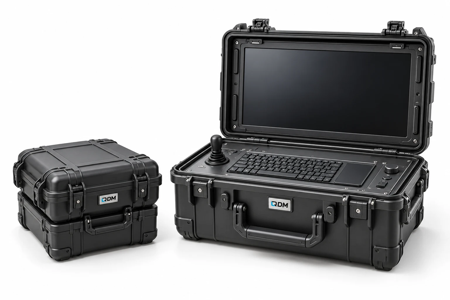
A transport-case concept for integrating operator equipment into a portable workstation.
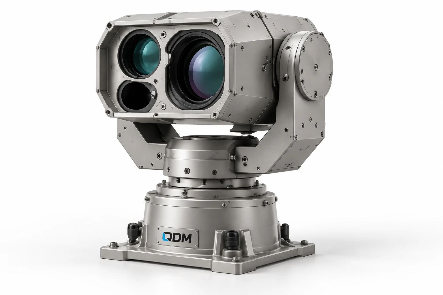
A mechanical positioning concept for customer-selected cameras, instruments or sensor payloads.
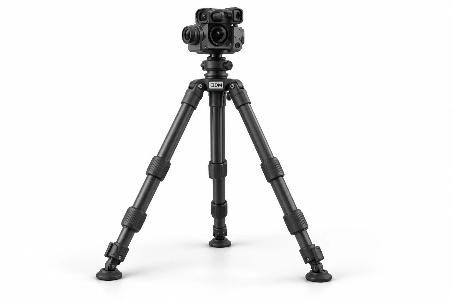
An adjustable support concept for securely positioning customer-selected instruments.