
Payload and motion
Define mass, centre of gravity, movement range and positioning objectives.
A mechanical positioning concept for customer-selected cameras, instruments or sensor payloads.
Enquire about this conceptMechanical integration concept · Configuration agreed per project
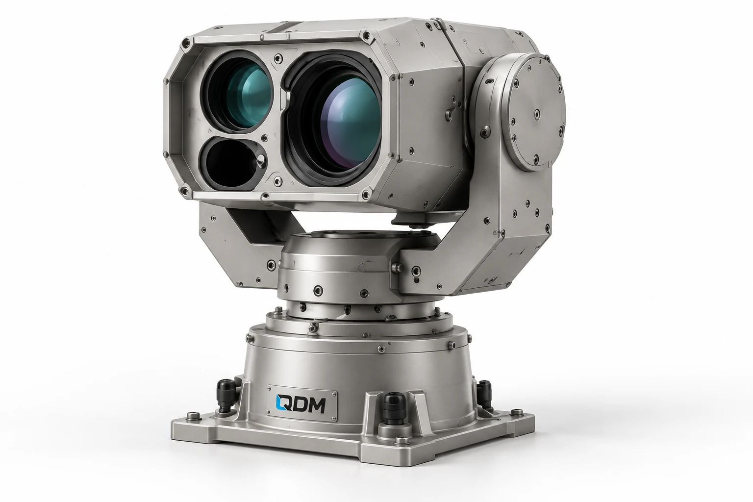
The pan–tilt study shows a supported payload with rotational positioning axes. The mechanical development scope can include the structure, bearings, drive interfaces, mounting and cable-management arrangement. Payload selection, motion requirements and any specialist electronics are defined for the project.
Define mass, centre of gravity, movement range and positioning objectives.
Develop supports, bearing arrangements, drive interfaces and mounting.
Agree cable routing, protection and interfaces to customer-selected equipment and controls.
Materials, dimensions, operating range, output, controls and delivery scope are confirmed in the project proposal.
Use these notes to define the application before choosing the final equipment configuration.
A pan–tilt mechanism turns an instrument about horizontal and vertical positioning axes. Commercial units use different mounting arrangements for cameras and other payloads. QDM’s mechanical concept can be developed for the customer’s instrument, with mounting geometry and load balance reviewed before selecting the drive and support components.
Payload mass alone is not enough to define the mechanism. Include its centre of gravity, size, cable connections and desired movement range. Speed and angular position requirements should be stated with the operating conditions. A top-mounted and side-mounted instrument may place different loads on the same axis arrangement.
Development should review the full movement envelope, cable routing, stops and holding behaviour with a representative payload. Agree how position is measured and whether movement is manually controlled or coordinated by an external system. Specialist electronics and control interfaces can be scoped with the customer team. The reference view does not provide a universal angular precision or environmental rating.
The table identifies the reference arrangement and the values to agree for your application.
| Parameter | Configuration / value | Confirm before manufacture |
|---|---|---|
| Payload | Defined mass and centre of gravity | Provide mounting drawing and services |
| Mounting arrangement | Top or side interface as scoped | Review load distribution |
| Pan and tilt travel | Defined in degrees | Confirm limits and clearance |
| Speed objective | Defined in degrees/s | Agree movement and settling task |
| Position target | Application-specific angular requirement | Define feedback and test method |
| Cable routing | Configured through the motion envelope | Review service loops and connectors |
| Control interface | Manual or external coordination as agreed | Define partner and client responsibilities |
These products are customizable. Configuration values and images are indicative and may change with the application. Final dimensions, components, controls and performance requirements are confirmed in the agreed project specification.
Representative CAD and generated design visualizations. These are not photographs of delivered equipment. Illustrated arrangements may change with customization; final values and visuals are confirmed in the project specification.
Send payload dimensions and mass, mounting, required motion, accuracy objective and operating conditions.
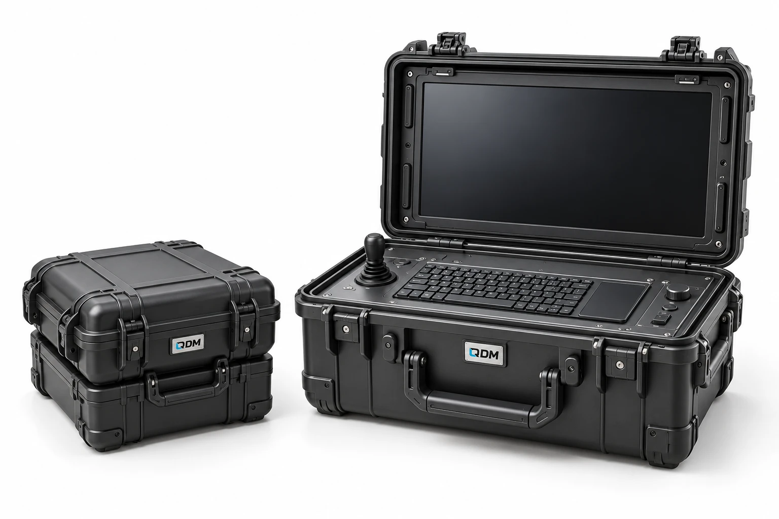
A transport-case concept for integrating operator equipment into a portable workstation.
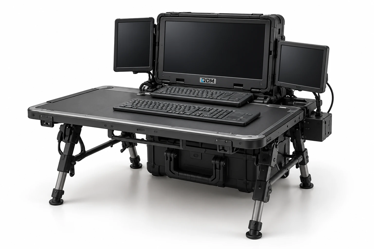
A folding work-surface and equipment-support concept for field deployment.
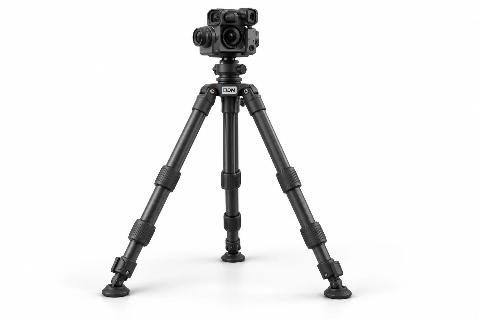
An adjustable support concept for securely positioning customer-selected instruments.