
Equipment integration
Define the customer-selected equipment, interfaces and mounting needs.
A transport-case concept for integrating operator equipment into a portable workstation.
Enquire about this conceptMechanical integration concept · Configuration agreed per project
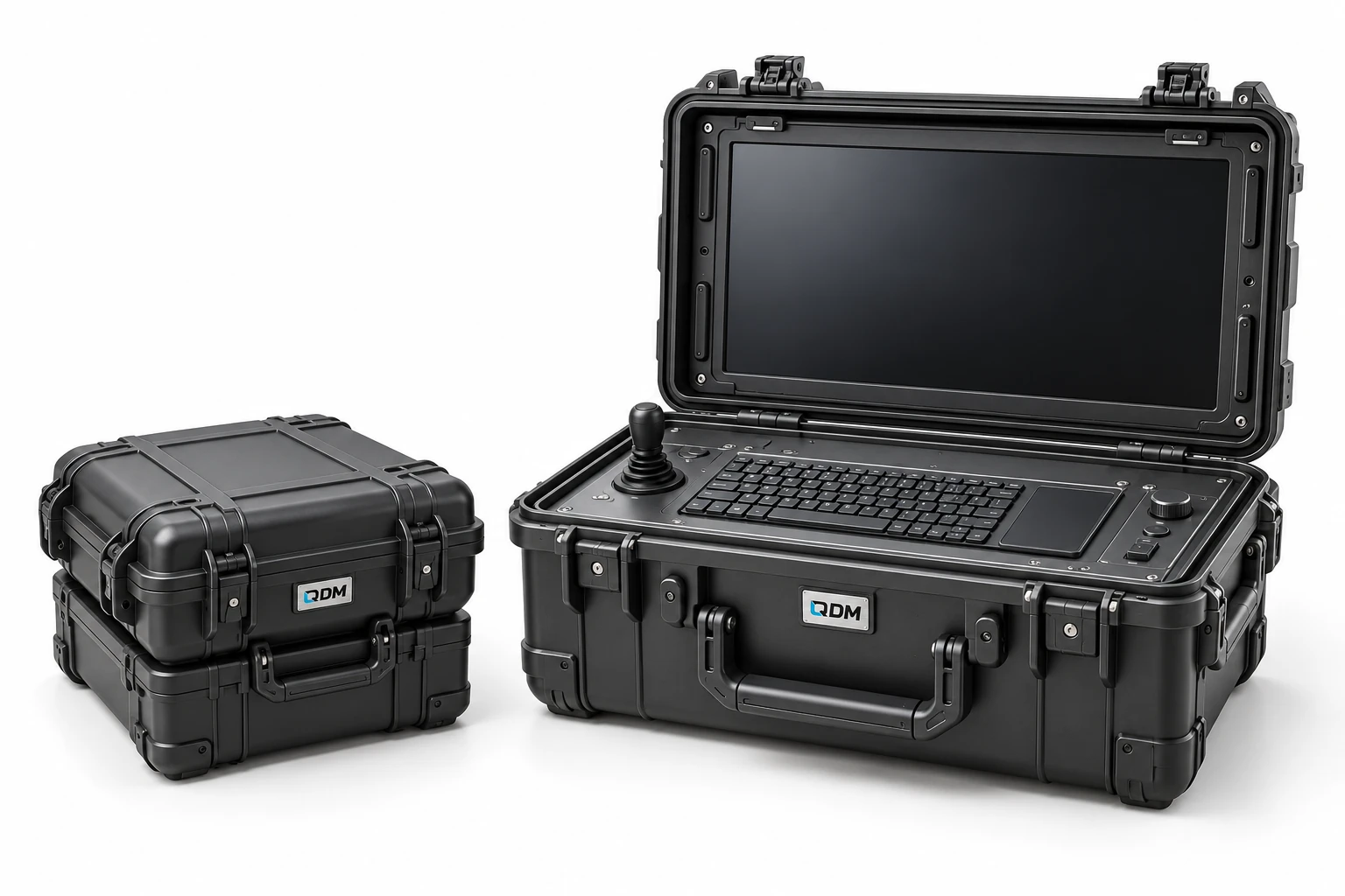
This field-system concept places operator equipment inside a carrying-case architecture. QDM’s mechanical scope can cover enclosure layout, mounting, connector access and transport protection around customer-selected equipment. Electronics, communications and performance requirements are separate project inputs.
Define the customer-selected equipment, interfaces and mounting needs.
Develop the case layout, access, supports and transport arrangement.
Agree the operating environment and any required verification with the relevant specialists.
Materials, dimensions, operating range, output, controls and delivery scope are confirmed in the project proposal.
Use these notes to define the application before choosing the final equipment configuration.
A portable equipment station combines a transport arrangement with a working layout for specified instruments or devices. Deployable case systems demonstrate the value of planning storage and working positions together. QDM’s concept is a neutral mechanical integration platform; it does not establish a military qualification, weather rating or included sensor package.
Start with an inventory of the components and how each is accessed. Transport size, lifted mass, cable routes and setup sequence influence the frame and packaging. Define whether equipment remains installed during transport or is removed for operation. Electrical power, cooling and communications should be identified as project interfaces where needed.
A development review should follow the actual sequence from transport to setup, use and packing away. Check handles, locking features, supports and cable access with representative component sizes and loads. Agree environmental or transport tests only where they form part of the scope. QDM can develop the enclosure and mechanical arrangement around the specified equipment and operating environment.
The table identifies the reference arrangement and the values to agree for your application.
| Parameter | Configuration / value | Confirm before manufacture |
|---|---|---|
| Equipment inventory | Client-specified devices and accessories | Provide dimensions and mounting data |
| Transport envelope | Configured in mm | Confirm vehicle or storage constraints |
| Carried mass | Defined in kg | Review handles and handling method |
| Operating layout | Application-specific | Define access and setup sequence |
| Mounting interfaces | Dedicated brackets and supports | Agree component locations |
| Services | Power and cable interfaces as scoped | Confirm electrical partner responsibilities |
| Environmental requirements | Defined and verified per project | Do not infer ratings from imagery |
These products are customizable. Configuration values and images are indicative and may change with the application. Final dimensions, components, controls and performance requirements are confirmed in the agreed project specification.
Representative CAD and generated design visualizations. These are not photographs of delivered equipment. Illustrated arrangements may change with customization; final values and visuals are confirmed in the project specification.
Send the equipment list, mounting envelopes, connector access, transport constraints and use environment.
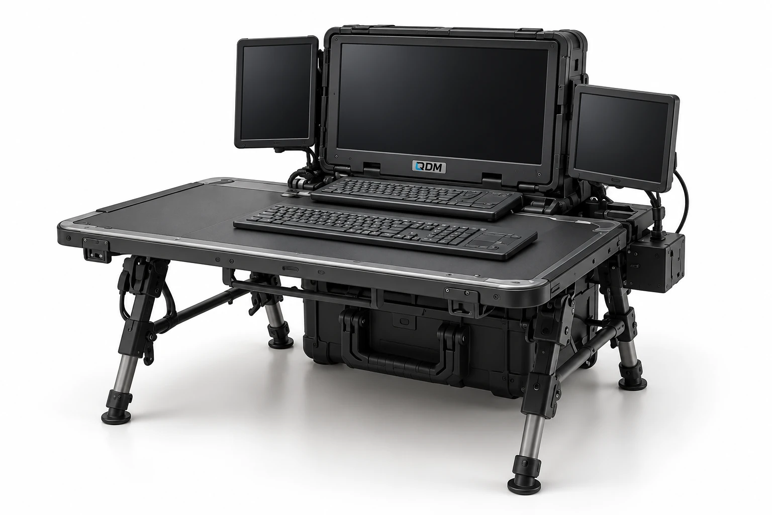
A folding work-surface and equipment-support concept for field deployment.
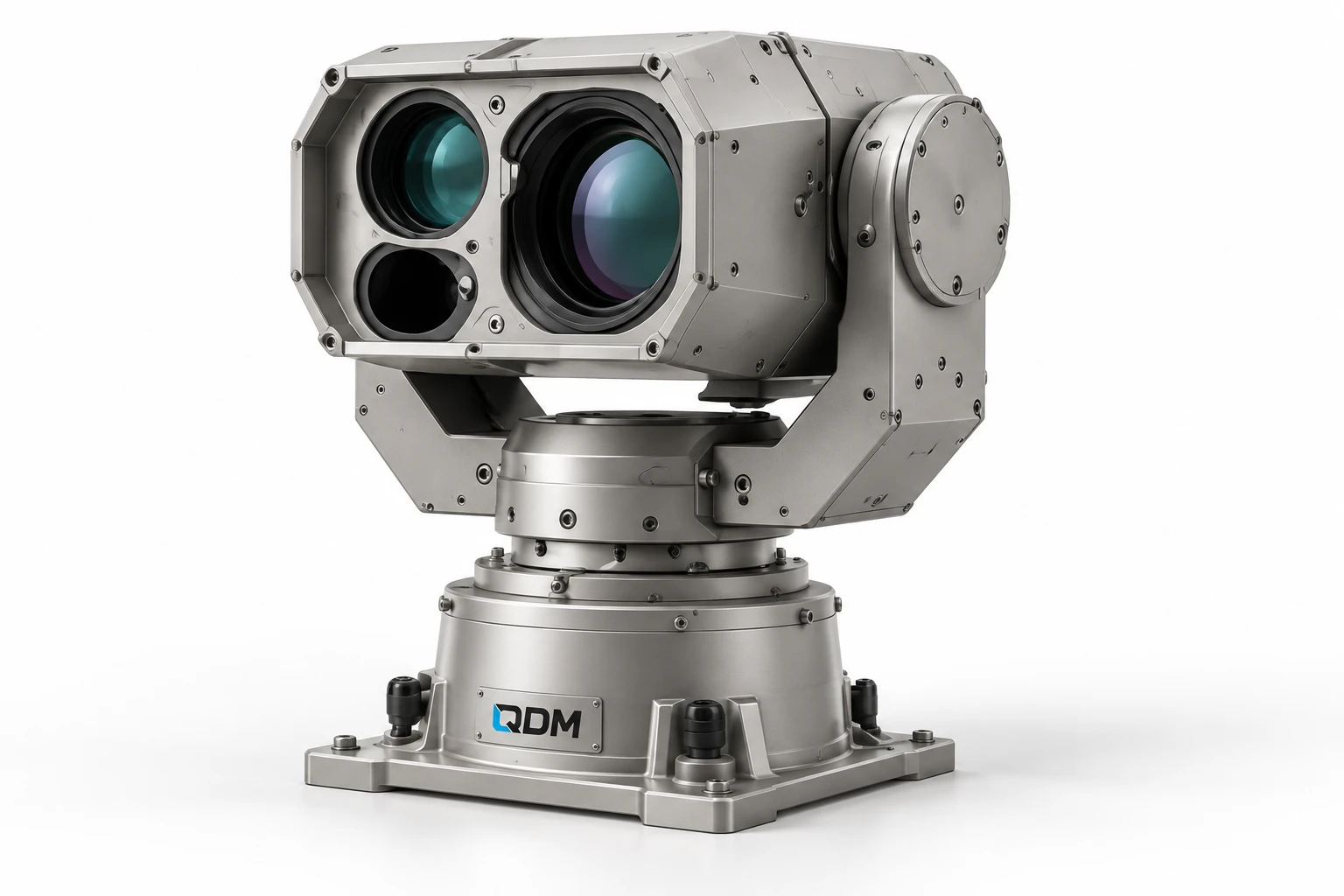
A mechanical positioning concept for customer-selected cameras, instruments or sensor payloads.
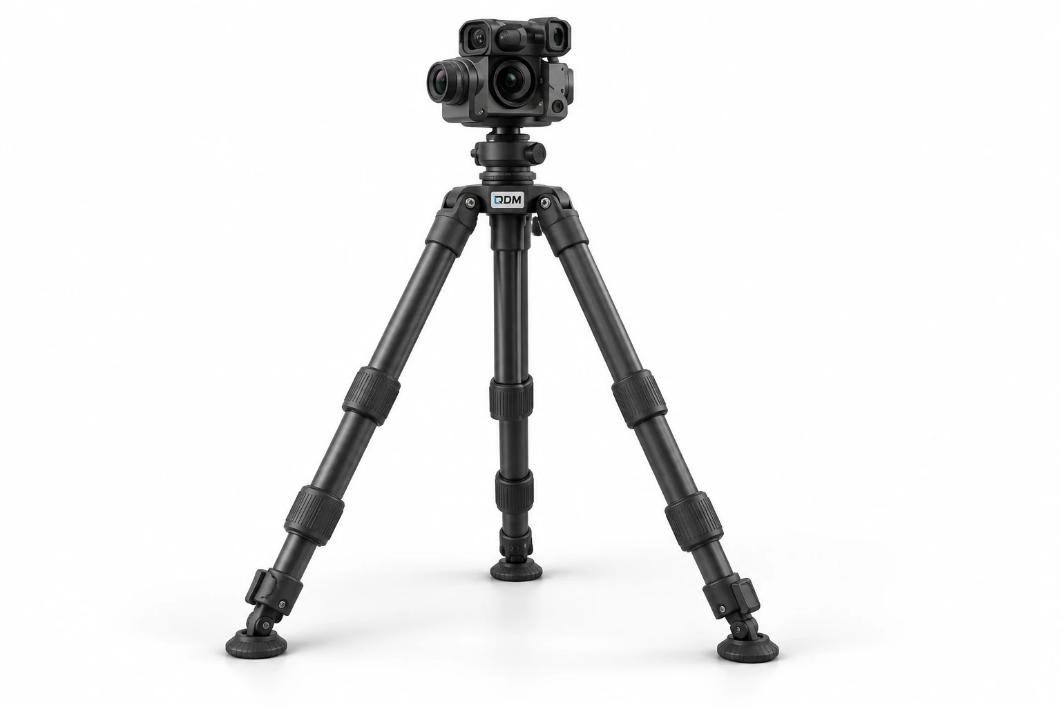
An adjustable support concept for securely positioning customer-selected instruments.