
← Packaging, Labelling and Film Processing Machines
Custom machinery / Design example

Slitting & winding machine

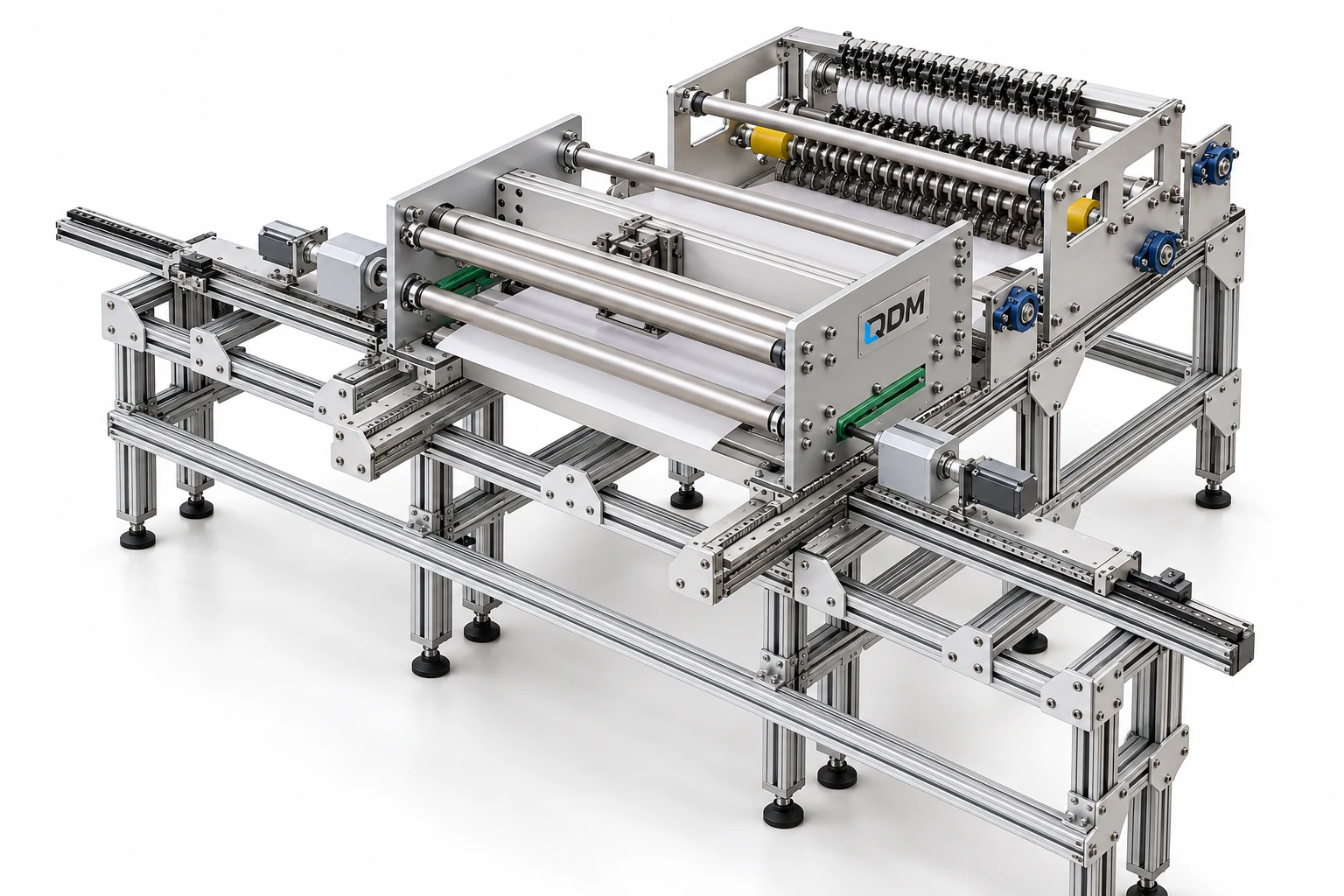
A dedicated mechanical layout for a bandage-material slitting and rewinding application.

Discuss a similar requirement

Application-specific mechanical development

Representative QDM slitting & winding machine design visualization
Slitting & winding machine — studio design view · Representative design visualization
Mechanical scope

What the design illustrates.

A mechanical layout for feeding, slitting and rewinding bandage material.

This example illustrates machine design and component arrangement. Process parameters, material compatibility, guarding, controls and final acceptance criteria require an application-specific scope.

  • Material feed and roller layout
  • Slitting and winding mechanism arrangement
  • Machine structure and mechanical access
Related capability

Machine design & development

Machines built around your process.

These products are customizable. Configuration values and images are indicative and may change with the application. Final dimensions, components, controls and performance requirements are confirmed in the agreed project specification.

Explore the service
Application & engineering guide

Slitting and rewinding bandage material

Use these notes to define the application before choosing the final equipment configuration.

Working principle

A slitting and winding machine feeds a continuous material, divides it into the required widths and collects the resulting strips. QDM’s source design was developed as a mechanical layout for bandage material. General slitting equipment illustrates the role of unwind, cutting and rewind functions; the material path and tooling still need application-specific development.

Configuration decisions

Provide the bandage or textile construction, incoming web width and required strip sizes. Stretch, compressibility and fraying affect the feed and cutting choices. Roll core, diameter and desired winding condition determine collection supports. Tension and guiding should be considered across the whole path, rather than specified only at the cutting point.

Planning the first build

A prototype trial should examine cut edges, strip width and the final roll using representative material. Agree the measurement method and acceptable winding condition. Include loading, adjustment and access to the selected cutters in the machine scope. This portfolio example concerns mechanical development; it does not establish medical-device approval, material qualification or a verified production output for the finished system.

Technical reading

These manufacturer references explain equipment principles. Their specifications describe their own products and are not QDM ratings or evidence of a partnership.
Project-specific technical parameters

Values to define before the build.

The table identifies the reference arrangement and the values to agree for your application.

Slitting and rewinding bandage material — configuration parameters
ParameterConfiguration / valueConfirm before manufacture
Source applicationBandage-material mechanical layoutConfirm intended material and use
Incoming webDefined width and thickness in mmProvide sample and roll data
Strip widthsApplication-specific in mmAgree tolerance and cutting arrangement
Cutting methodSelected for the materialDefine acceptable edge condition
Web tensionConfigured for feed and windingReview stretch and guiding
Rewind formatDefined core, diameter and roll conditionAgree loading and collection
AcceptanceCut and winding trials as scopedDefine inspection and test material

These products are customizable. Configuration values and images are indicative and may change with the application. Final dimensions, components, controls and performance requirements are confirmed in the agreed project specification.

Your application

Define the next build.

Share the function, product or material, interfaces and acceptance objective. Feasibility, prototype and manufacture can be separately scoped.

Email us about your project
More design examples

Explore the portfolio.

All machines & projects
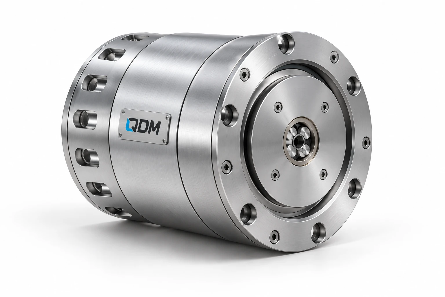
Representative QDM custom actuator design: assembly view
Motion systems

Custom actuator design

Application-specific mechanical and electromechanical actuator development, from transmission and motor interfaces to working prototypes.

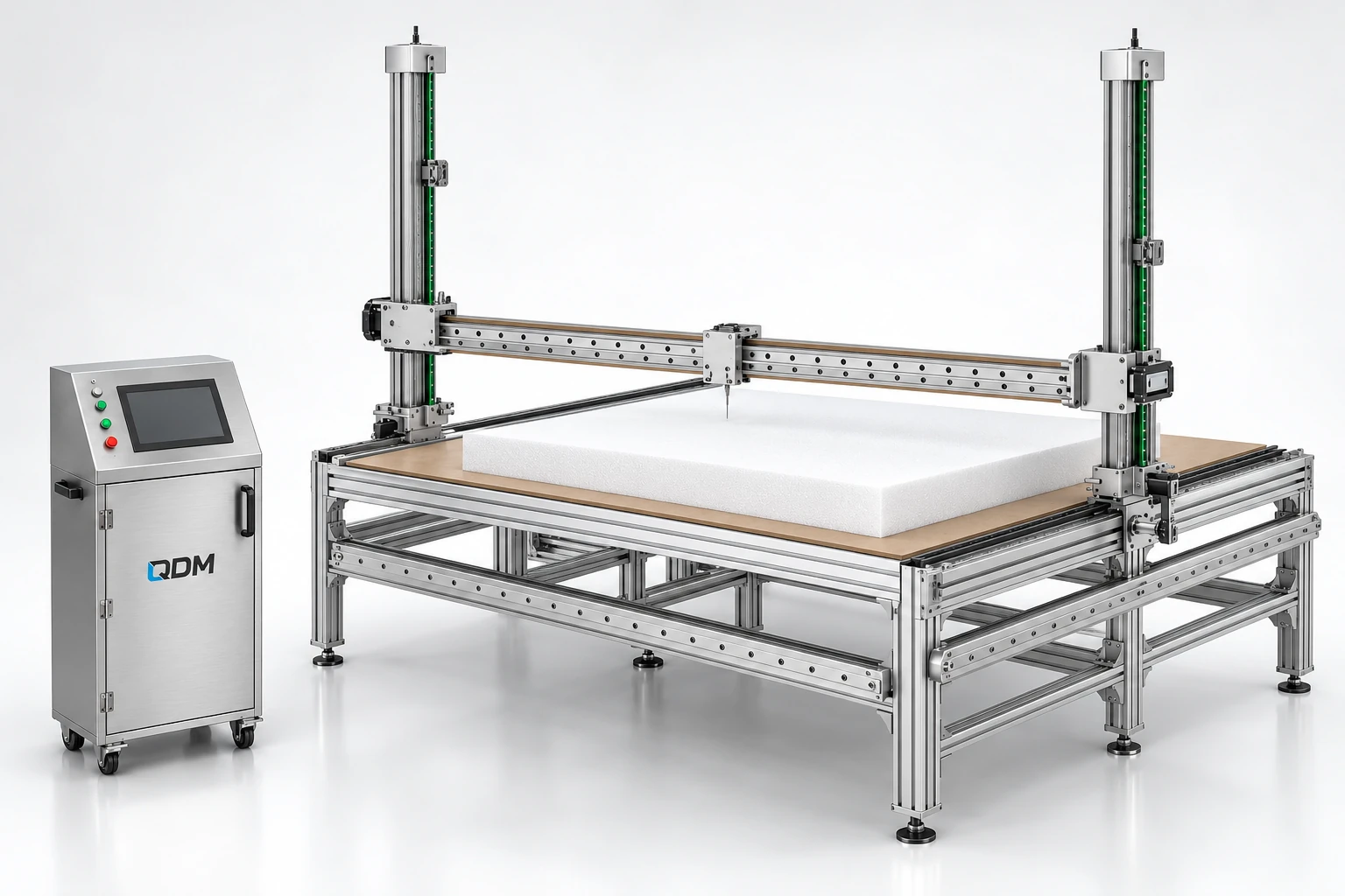
Representative QDM four-axis foam cutter design visualization
Custom machinery

Four-axis foam cutter

A machine frame and coordinated motion arrangement for a foam cutting application.

WhatsApp