
← R&D and Prototype Projects
Custom machinery / Design example

Four-axis foam cutter

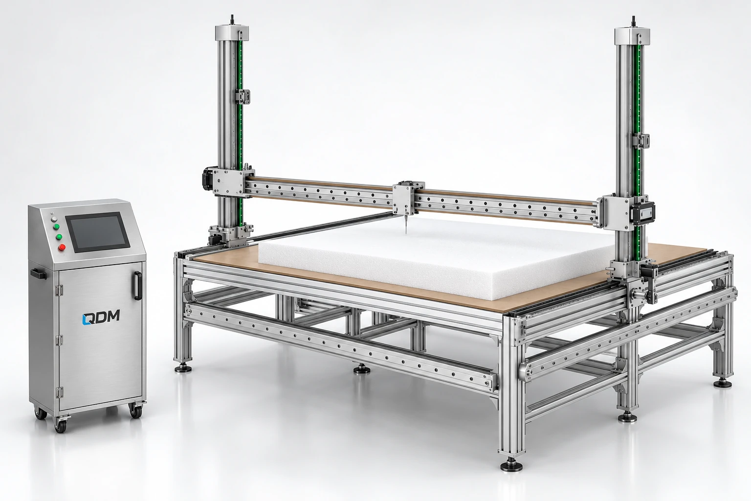
A four-axis foam-cutting machine design illustrating a custom structure and motion-system layout.

Discuss a similar requirement

Application-specific mechanical development

Representative QDM four-axis foam cutter design visualization
Four-axis foam cutter — studio design view · Representative design visualization
Mechanical scope

What the design illustrates.

A machine frame and coordinated motion arrangement for a foam cutting application.

This is a mechanical CAD design example. Working dimensions, cutting process, control system and material requirements are agreed for the intended application.

  • Machine frame and working area
  • Coordinated axis arrangement
  • Manufacturing and assembly considerations
Related capability

Machine design & development

Machines built around your process.

These products are customizable. Configuration values and images are indicative and may change with the application. Final dimensions, components, controls and performance requirements are confirmed in the agreed project specification.

Explore the service
Application & engineering guide

A coordinated motion frame for foam cutting

Use these notes to define the application before choosing the final equipment configuration.

Working principle

A four-axis foam cutter coordinates movement around a supported foam workpiece. QDM’s example illustrates a frame, working area and mechanical motion arrangement. Foam cutting equipment can use a hot wire or another selected process, but the illustrated structure does not by itself confirm the cutting method or compatibility with every foam material.

Configuration decisions

Specify the foam type, workpiece envelope and required shape before choosing the tool. The cutting process determines clearance, feed behaviour and any thermal or debris-management requirement. Axis travel, support and work holding should be developed together. A four-axis designation describes coordinated movement; it is not a tolerance or a promise of a particular finished surface.

Planning the first build

A first development stage should confirm material suitability and review a representative cutting task. Agree the output shape, dimensional acceptance and inspection method, then define controls and utilities for the chosen process. QDM can develop the custom frame and manufacturing scope around those decisions. Final travel, operating speed and process values are established for the agreed configuration and verified during the scoped trials.

Technical reading

These manufacturer references explain equipment principles. Their specifications describe their own products and are not QDM ratings or evidence of a partnership.
Project-specific technical parameters

Values to define before the build.

The table identifies the reference arrangement and the values to agree for your application.

A coordinated motion frame for foam cutting — configuration parameters
ParameterConfiguration / valueConfirm before manufacture
Motion arrangementFour-axis reference conceptDefine coordinated movement required
Cutting processSelected for the applicationConfirm hot-wire or other tool method
Foam materialClient-specific type and propertiesReview suitability and sample trial
Working envelopeConfigured in mmProvide maximum blank and shape
Tool and work holdingApplication-specificReview clearance and support
Cut objectiveDefined dimensions and surface resultAgree inspection method
Controls and utilitiesScoped for the selected processDefine specialist responsibilities

These products are customizable. Configuration values and images are indicative and may change with the application. Final dimensions, components, controls and performance requirements are confirmed in the agreed project specification.

Your application

Define the next build.

Share the function, product or material, interfaces and acceptance objective. Feasibility, prototype and manufacture can be separately scoped.

Email us about your project
More design examples

Explore the portfolio.

All machines & projects
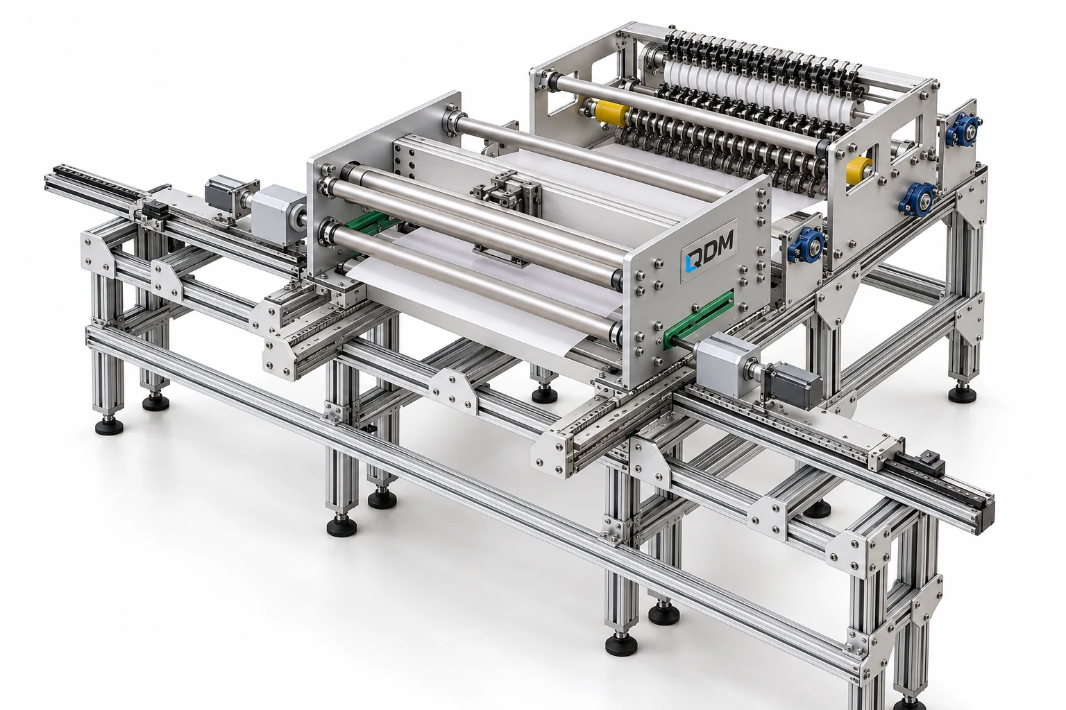
Representative QDM slitting & winding machine design visualization
Custom machinery

Slitting & winding machine

A mechanical layout for feeding, slitting and rewinding bandage material.

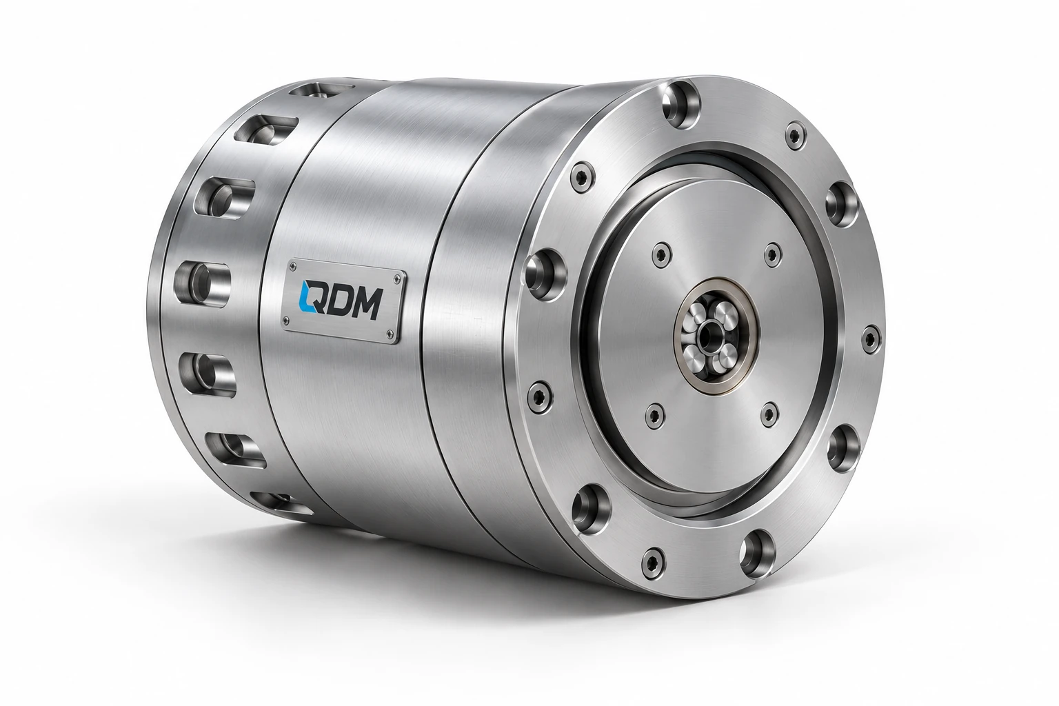
Representative QDM custom actuator design: assembly view
Motion systems

Custom actuator design

Application-specific mechanical and electromechanical actuator development, from transmission and motor interfaces to working prototypes.

WhatsApp