Web and roll format
Define material construction, incoming roll and required finished widths and rolls.
A roll-fed converting architecture with guided material travel and multiple winding positions.
Enquire about this machineMachine & device catalog · Configuration agreed per project
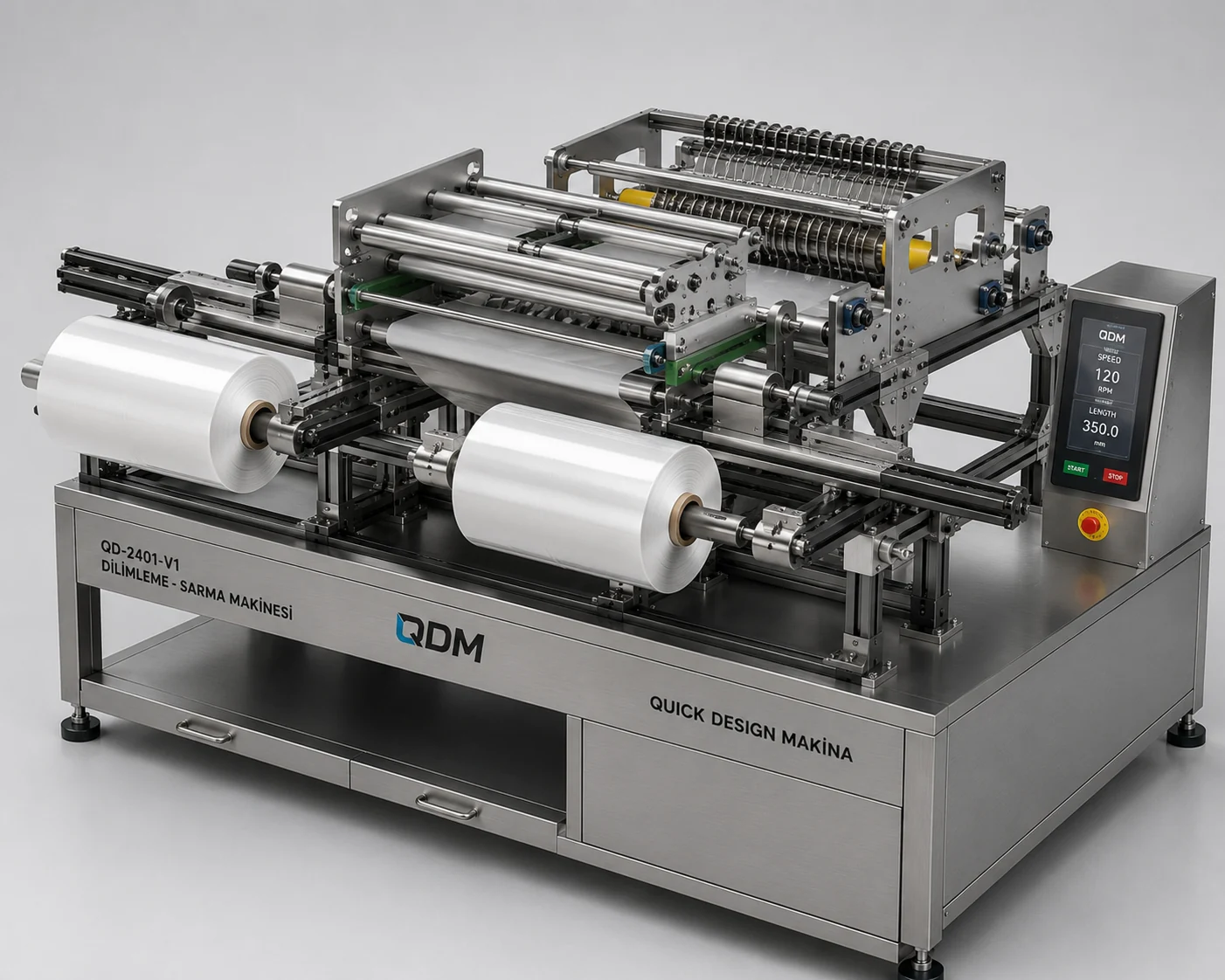
The roll-converting study develops material feed, guide rollers, slitting positions and rewinding into one mechanical layout. Its enclosure and roll arrangements show an alternative configuration within QDM’s cutting and winding work. Material behaviour and the finished roll format determine the required web path, tooling and tension-control scope.
Define material construction, incoming roll and required finished widths and rolls.
Develop guides, cutting positions, access and the winding-shaft arrangement.
Agree drive, tension, guarding and application-specific verification requirements.
Materials, dimensions, operating range, output, controls and delivery scope are confirmed in the project proposal.
Use these notes to define the application before choosing the final equipment configuration.
A roll converting system moves a continuous material through an agreed operation and into a collected roll or other output. Unwind, guiding and rewind are separate mechanical functions. Slitting systems illustrate how a wide web can be divided and rewound, but the QDM converting concept should be scoped from the actual material and required treatment.
State web width, thickness, flexibility and surface sensitivity. The incoming roll and final roll dimensions affect supports and handling. Tension must suit the material throughout the process; a configuration for a stiff strip may not work for a stretchable film or textile. Identify whether slitting, coating, inspection or another operation is required before selecting modules.
Development should begin with a material-path drawing and representative web samples. Review guiding, contact marks, tension adjustment and the final roll condition at the intended operating points. Agree a method for loading rolls and accessing the working zone. QDM can coordinate a custom frame and modules around the specified conversion task, with speed and output verified for that configuration.
The table identifies the reference arrangement and the values to agree for your application.
| Parameter | Configuration / value | Confirm before manufacture |
|---|---|---|
| Web material | Client-specific roll-fed material | Provide sample and properties |
| Web width and thickness | Defined in mm | Review support and process zone |
| Incoming roll | Diameter, core and mass as specified | Confirm mounting and loading |
| Conversion task | Application-specific operation | Define module sequence |
| Tension | Defined in N or agreed control basis | Review stretch and surface sensitivity |
| Final roll or output | Configured to the requirement | Agree collection geometry |
| Operating speed | Defined in m/min | Verify with material and operation |
These products are customizable. Configuration values and images are indicative and may change with the application. Final dimensions, components, controls and performance requirements are confirmed in the agreed project specification.
Representative CAD and generated design visualizations. These are not photographs of delivered equipment. Illustrated arrangements may change with customization; final values and visuals are confirmed in the project specification.
QDM supplies equipment with a standard one-year machine warranty, starting from commissioning.
Purchased components are covered under the relevant manufacturer’s warranty terms. Two-year component coverage applies where provided by the manufacturer; coverage and start dates follow those terms.
Extended warranty and maintenance agreements can be arranged for the project. Coverage, duration, service responsibilities and commercial terms are agreed in the contract.
The quotation and contract define the equipment covered, the applicable warranty terms and the agreed service arrangements.
Include material samples, incoming roll details, finished widths, winding format and the intended operating conditions.
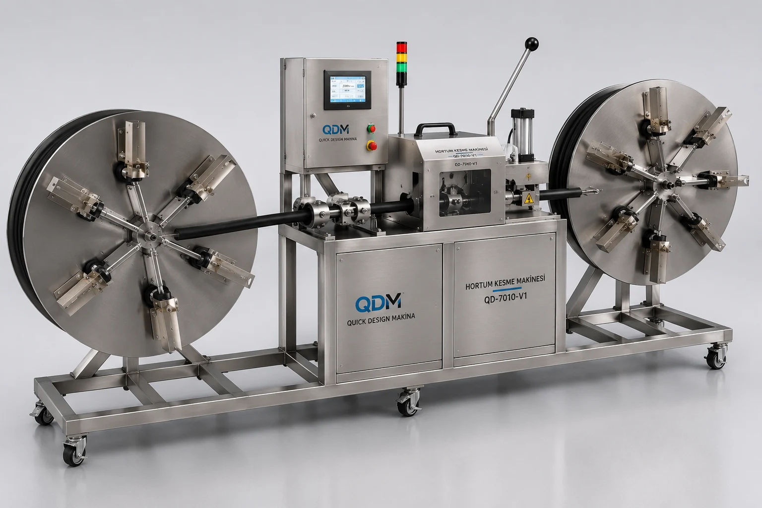
A mechanical layout combining reel support, hose feeding and a central processing station.
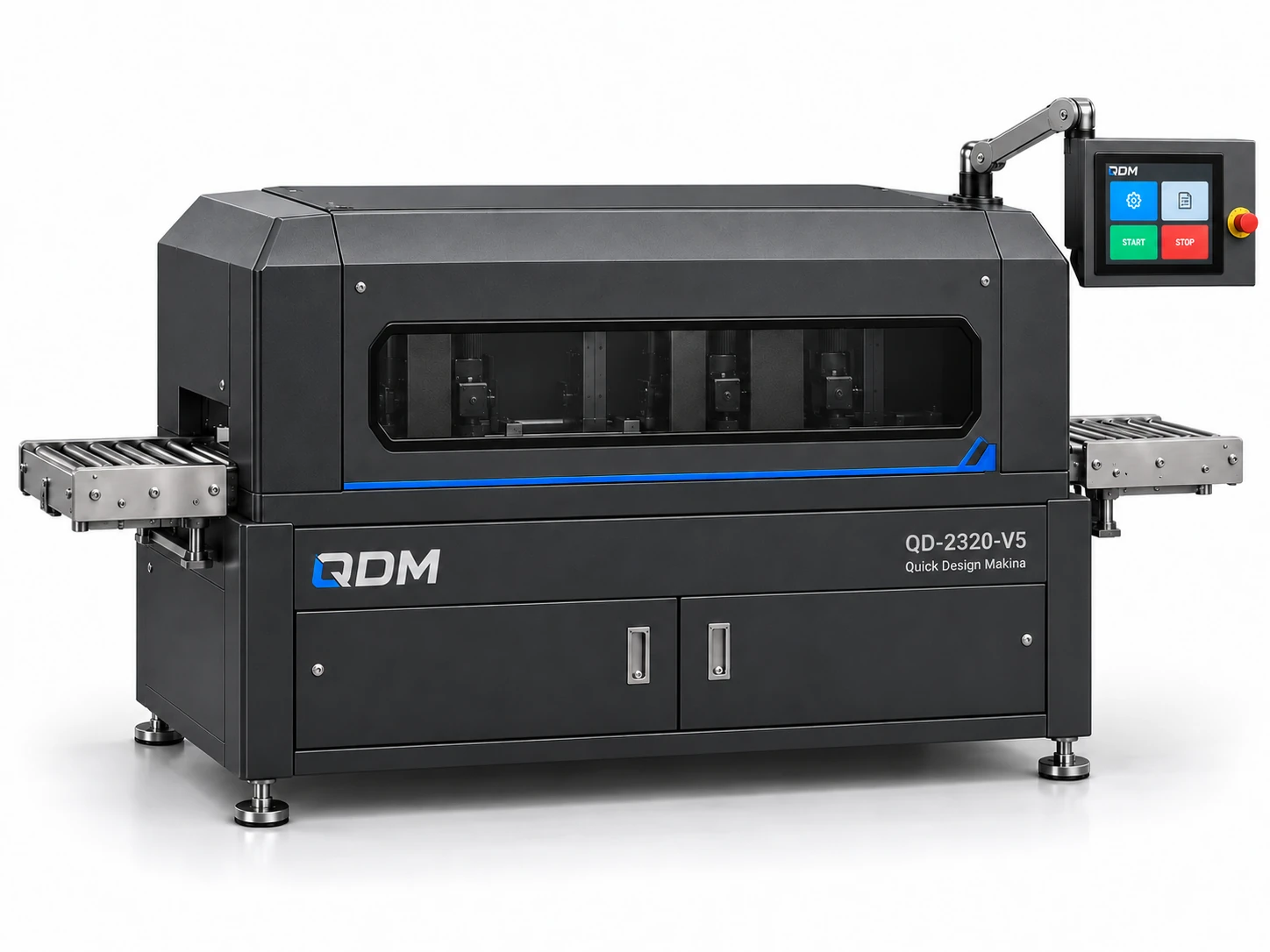
A multi-station machine layout for application-specific sanding and surface finishing.