Part and finish
Define material, geometry, surfaces to process and an acceptable reference finish.
A multi-station machine layout for application-specific sanding and surface finishing.
Enquire about this machineMachine & device catalog · Configuration agreed per project
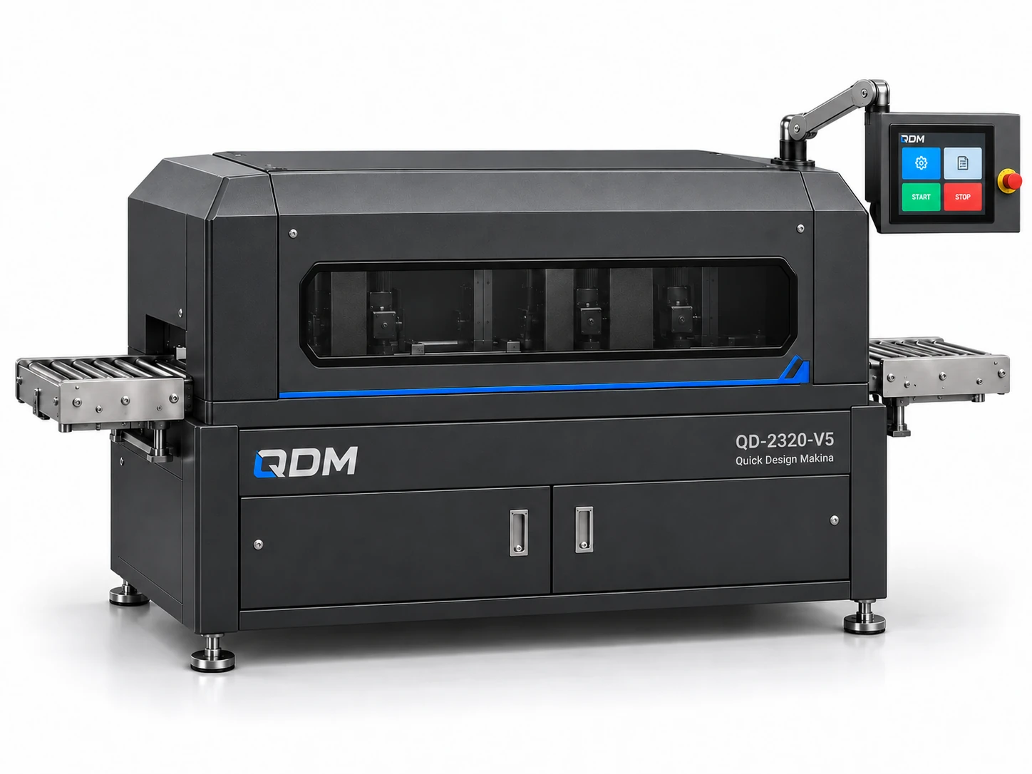
The surface-finishing study combines several belt-based working positions in a guarded metal enclosure with a through-feed product path. The equipment is developed around the workpiece, accessible surfaces and desired finish. Abrasives, tooling, part support and extraction requirements are agreed for the actual material and operation.
Define material, geometry, surfaces to process and an acceptable reference finish.
Develop abrasive positions, part guidance and the sequence of working operations.
Scope workholding, handling, extraction, access, maintenance and controls.
Materials, dimensions, operating range, output, controls and delivery scope are confirmed in the project proposal.
Use these notes to define the application before choosing the final equipment configuration.
A surface finishing machine applies a controlled abrasive process to a workpiece. Industrial finishing equipment uses arrangements such as abrasive belts and brushes for selected material and geometry. QDM’s reference concept provides a basis for developing the support, drive and contact arrangement around the actual metal component and intended surface result.
Deburring, a directional finish and removal of a surface layer are different objectives. Provide the starting condition and, where possible, a reference sample of the result. Part size, thickness and rigidity affect how the workpiece is supported. Abrasive selection, contact pressure, feed and debris collection should be reviewed together for the chosen operation.
Prototype trials should use representative parts and an agreed assessment method. A visual finish can be compared with an approved sample; a dimensional or roughness target needs a defined measurement procedure. Include consumable replacement and adjustment access in the machine brief. QDM can scope the mechanism and supporting equipment without assigning one surface-quality or throughput rating to every configuration.
The table identifies the reference arrangement and the values to agree for your application.
| Parameter | Configuration / value | Confirm before manufacture |
|---|---|---|
| Workpiece | Specified metal and initial condition | Supply sample or drawing |
| Part envelope | Defined in mm | Confirm thickness and support |
| Process objective | Deburring, finishing or agreed treatment | Approve target result |
| Abrasive arrangement | Selected belt, brush or tool | Review material and contact |
| Feed or working speed | Defined per process | Establish through application trials |
| Quality criterion | Sample, dimensions or roughness as agreed | Define inspection method |
| Debris and consumables | Application-specific support | Agree extraction and replacement access |
These products are customizable. Configuration values and images are indicative and may change with the application. Final dimensions, components, controls and performance requirements are confirmed in the agreed project specification.
Representative CAD and generated design visualizations. These are not photographs of delivered equipment. Illustrated arrangements may change with customization; final values and visuals are confirmed in the project specification.
QDM supplies equipment with a standard one-year machine warranty, starting from commissioning.
Purchased components are covered under the relevant manufacturer’s warranty terms. Two-year component coverage applies where provided by the manufacturer; coverage and start dates follow those terms.
Extended warranty and maintenance agreements can be arranged for the project. Coverage, duration, service responsibilities and commercial terms are agreed in the contract.
The quotation and contract define the equipment covered, the applicable warranty terms and the agreed service arrangements.
Send part drawings, material, photographs of the starting and desired finish, required operations and intended throughput.
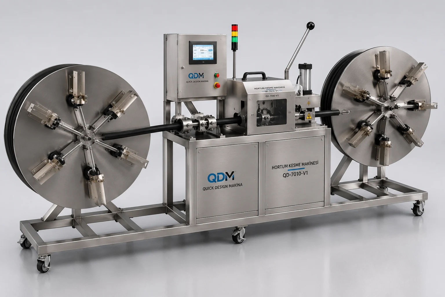
A mechanical layout combining reel support, hose feeding and a central processing station.
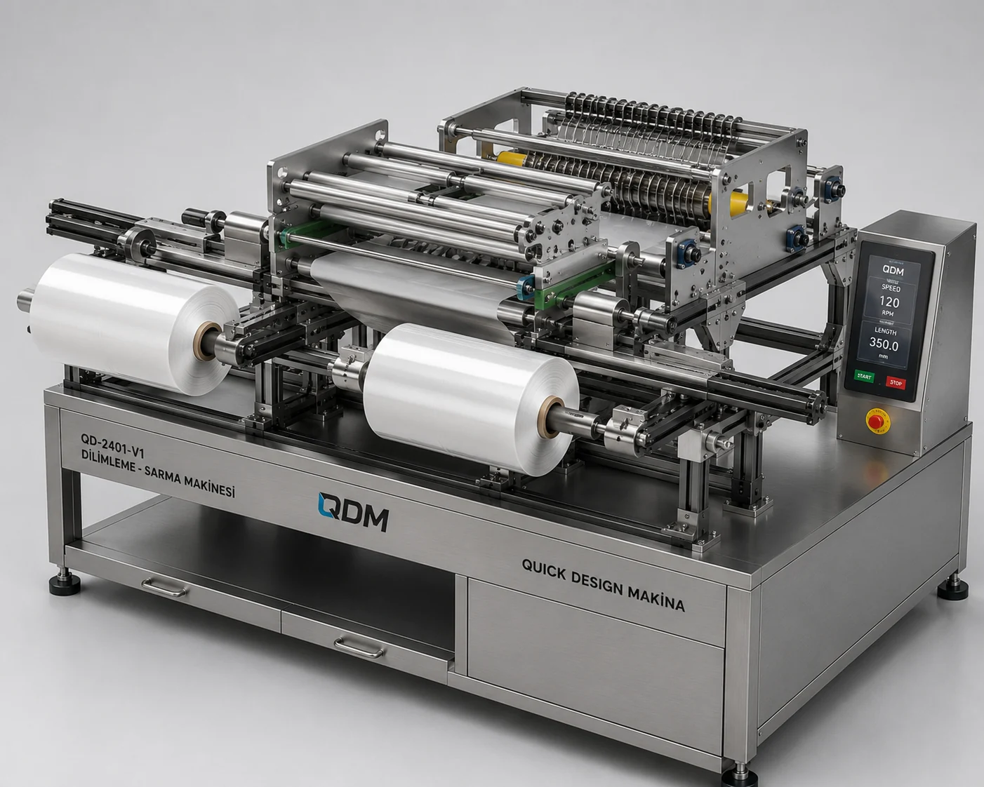
A roll-fed converting architecture with guided material travel and multiple winding positions.